Arduino is pretty handy for low powered projects and is cost-effective (against Raspberry Pi). Not being able to connect to a network natively is a big challenge in applying Arduino for most use cases. While, Arduino has a Ethernet Shield for quite a while, it is impractical to expect a Ethernet port at every point an Arduino would be required. I do have Ethernet-over-Power (EoP) at home to extend its reach, but still didn't scale for me (the over all cost will also include a EoP adapter).
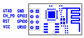
ESP8266 is an effective way to connect Arduino to a Wifi network. It is not a Arduino specific shield. It is a general purpose module that could be mixed with any other micro controller unit/circuit. All you need is a UART communication support on the other end (which almost all micro controllers have built-in). The added advantage is the cost, form-factor (unlike other shields) and just uses 2 pins from the Arduino (RX/TX of UART). The ESP8266 module is pretty small, but does its job well.
ESP8266 Wifi Module
Once powered appropriately, you could communicate with the ESP8266 module via serial communication (@9600 baudrate, at least my version of ESP8266). The Wifi configuration/data everything is then communicated via the extensions to a standard AT command set. This being UART based, its going to be imposing restrictions on the rate of transfer of data (but might not matter for most use-cases) -- just to highlight the difference against a USB or SoC based Wifi implementation.
ESP8266 PinOut
The module does have a built-in TCP/IP stack, so we don't have to worry about that -- that's why we do get response to ping automatically (as shown in the video below). It is not full-fledged though; provides basic connectivity over Layer4 -- good enough. It does have its own DHCP client as well.
There is a open-source library for ESP8266 for Arduino:
Here is the video showing my project in action :) Arduino joins my home Wifi network; shows its own IP on the LCD; runs a TCP server at port 1555 and waits to accept new connections. I connect from my desktop Ubuntu and send a message which shows up correctly on the Arduino LCD.
This is going to be a cool extension to my geyser control project now -- I should be able to control my geyser from anywhere and more importantly time it based on the needs. Some sort of security needs to be worked out.
Watch my previous post on a prototype project using Raspberry Pi. Now you would know what was that prototype for.
Yes, I now have built a power strip that is completely controllable by a Raspberry Pi over network.
The idea of controlling a power strip over network is nothing new, but this is certainly a unique one and I needed this badly. I have built a power strip with more features than the off-the-shelf ones and they were at least twice as expensive as what it took me to build this one. I can fix any problem in this device from software to a relay to a resistor -- in case any of these is blown. Oh yeah, the happiness of building something yourself is invaluable :)
To me, one of the driving factors for such a device is: We have Tata Sky+ HD at home and we record TV programs left and right. It has almost reached a point that we don't watch live content except news (for the time comfort and sake of skipping ads). Many interesting series do come in the night, for which, we leave the set-top-box (STB) on -- naturally for prolonged time (till morning) even if the recording is just for an hour or so in the midnight. Tata Sky+ HD STB consumes 20+W of power even on standby. I wanted to avoid this waste of power, by having the ability to turn on/off the power sockets using a rather low power device.
Raspberry Pi consumes just around 3.5W and has complete networking support. With abundant GPIO pins, I can use it to control at least 8 different sockets. This is one of the main reasons for me to choose a Raspberry Pi. While I had worked on AVR based micro controllers, but getting a AVR board on the network would have been much more difficult than this. Also the power of Linux, provides numerous software that were of great use to me while building this (python, apache2, flask etc.,)
Some of the key features:
Power Sockets are controllable via a web interface, so available from any device on the network.
Web service supports REST based interaction for easy integration with any app that I might write in the future (at least for the android phones).
Core web and daemon logic on python that avoids cross-compilation work for Rs Pi architecture. Rewrite code easily and just drop it for deployment. This was awesome! God bless interpretors!
Ability to control sockets from the Internet once I VPN into my home network. (this should let us do the recording even when we are on vacation; how cool is it that I can turn a socket in Bangalore on or off, from anywhere in the world)
Timer support, so I can schedule a On or Off event after a while. Say, I can turn on a socket at midnight 12am, run it for an hour and turn it off! There is a dedicated power daemon that runs in the background to take care of scheduling these requests when its time.
The power sockets are still controllable using their dedicated switches, so you don't have to hunt for a browser to turn on the sockets.
Here is the power strip in action:
I have also now installed the power strip for the real purpose I wanted for. See the demo where I turn OFF my Tata Sky+ HD Set Top Box using the mobile.
I have taken photos all the way while I built this power strip. Stay tuned for lot more technical details (electronic circuits, hardware, software) with photos, on what went behind this power strip.
I have always had this excitement to control high-voltage devices from electronics. I could never do one because of lack of hardware and/or the scare for dealing with high voltage and getting it right the first time. Finally, I now have a proof of concept project that controls a 220v bulb from a Raspberry Pi. More details, maybe in a later post. Right now, I need to build a better actual project with this :)
Raspberry Pi runs on Raspbian Wheezy linux and the controlling code is written in Python.
Last weekend, I managed to complete a long-pending project of mine. The idea was to setup an infrastructure at home so I could watch TV from anywhere in my home (ie., network streaming via Wifi). I missed this facility particularly when we have guests at home and we couldn't watch TV at our convenience (second TV? No, there are differences and I don't need a second one right now).
Bottom line is, I now can watch TV anywhere in my house -- on my laptop, even on my mobile!! See this lenovo touch tablet showing Oreo Ad on Vijay TV:
I had always felt that I have everything I needed to do this, but it has not been that easy before I discovered all the right things. A simple way to put it would be: connect the video/audio output of the set-top-box to a TV tuner on a comp and stream it! But a number of questions need to be answered at every stage in this setup.
1. Video Output of Set-Top-Box: I needed a video output that is in parallel to the one that connected to my TV. I don't want to plug out and plug in every time I need to stream TV content. Fortunately, I have been using the component video of the STB for my TV due to its greater clarity, so the composite video was idling anyways. Cool.
2. Audio Output of Set-Top-Box: I had to use a splitter here, as the stereo audio output is connected to my home theatre already.
3. Connect it to the TV tuner: It is this stage that took me a while to figure out!! I had a TV tuner that I used and hacked long back. When it looked like everything was in place, I realized that the TV tuner only has a S-Video input and a RF antenna (cable) input. I would need a composite input socket and there is no easy conversion possible from composite to S-Video (ie., pin to pin mapping) due to the difference in the signals. I opened the TV tuner box and searched for any composite video input that probably didn't get exposed outside -- hoping I could solder them if required. This is the TV tuner motherboard:
Could not find any socket/pin for composite video. I found the TV tuner chip on the motherboard ie., Trident TVMaster. On downloading the datasheet of the chip, I could confirm that the chip in deed supports Composite video as input. The pin diagram in the datasheet had clear indication of I/O pins available for composite input. When I traced those lines from the chip on the motherboard, it ended up in the existing S-Video socket. This kind of contradicts! How could S-Video port provide a composite input?! After lots of reading, the conclusion was simple : my TV tuner uses a non-standard 9 pin S-Video socket (while a standard S-Video socket is just 4 pins -- Y, C, Gnd, Gnd). The 9-pin socket is compatible with the 4-pin S-video socket, so the remaining 5 pins could be used for other inputs. Some hardware (like my TV Tuner) use this for simplicity in its form-factor. So all I needed was a conversion cable from composite video to 9-pin S-Video -- note: this is just pin mapping, no real signal conversion. Fortunately got this simple cable from ebay. I had reached this point months back and the project stalled :D
4. TV tuner works? I had used this TV tuner against RF cable earlier, but never used/tested with composite video; and given all these conversion thingy, I wanted to first test if the TV tuner software works directly. And, yes it did!! I just had to configure the software to use the correct input signal. But TV tuner software doesn't stream, it just renders locally.
5. Stream it from VLC: TV tuner device creates a video device on the computer and the tuner software uses the same. My tuner creates a Video device called 'Trident Analog Video'. VLC supports playing/streaming of video devices via DirectShow. I had streamed webcam's earlier, so wasn't anything new here for me. Things that required attention was how to configure via VLC, to use the correct input (Composite) -- as this device supports multiple inputs (RF antenna, S-Video, Composite etc). VLC has 'advanced options' while streaming that lets us configure the device. Input signal had to be set as '1' for composite. Used 'avi' as the container, 'divx' as video codec, 'aac' as audio codec. I have a Asus EEEBox on my setup that is already connected to the TV for other usage. Due to its proximity to the set-top-box, I used my eeebox for this purpose too. It connects to my home network via Wifi, so it could be reached from anywhere in my house.
6. Play it from VLC: Now that the stream is on, all I need to do is connect to it via network. I used VLC again from a Lenovo touch tablet and connected to the eeebox via Wifi. Voila! I could now watch TV on my laptop. I'm yet to figure out an app for Android that could show multimedia stream over network -- given the small screen size, I am not that keen on watching TV on mobile. And as it has to go through the whole process of capture/encode/stream/network/decode/render, there is a delay of few seconds against the video on the live TV.
Some of you might have already thought about this: the only missing thing is that I can't change channels remotely. But it is just because I don't have a network remote, yet! (I have been eye-ing on Logitech Harmony Link for sometime :D).
There are so many types of video interfaces (ie., cables) that we come across every other day and not everyone understands what they are. It is essential to understand them, so we can use the best option that we have. There is definitely differences in the video quality and because these standards have evolved over time, not all video devices (be it a TV or a video player) have all available options. This has enforced the recent device manufacturers to support a variety of video interfaces, thus they ensure backward compatibility with the other end (a TV or a player). Unfortunately this has brought in confusion to the common people when they just look at the back of their new LCD TVs. Those olden days TV would just have one RF cable input, nothing else!! Gone are those days! Now, if you look at a modern TV, there are whole bunch of outputs (yes, including that RF cable input), and it isn't easy to choose the right cable to use for your need unless you understand what it means. Thanks to all those unique swanky colors, that lets us easily identify them on two devices.
It so happens that if both your devices (player/TV) are recent ones, you will have many choices. At that point, it becomes important to use the right one. Here are the various cables in the increasing order of their quality:
1. RF coaxial cable: This is the old one, that used to run from the Antenna on the terrace. This has the least quality. The TV Tuners for computer are exactly meant to decode this input. Carries both audio and video.
2. Composite (RCA): This is the most popular yellow plug thingy. Composite cable offers more quality than the coaxial ones. This is so very popular that, people still use this for video signals even when they have better options. That said, even today, this is still the most available option (in India). Many lower end DVD players/TVs only support till Composite. Carries only Video.
3. S-Video: The name apparently derives from the phrase 'Separated-Video'. In S-Video, the video signal is mainly separated into two parts: Chrominance (color) and Luminance (light intensity) signals. This offers much better clarity while solving some shortcomes in the composite signal. S-Video cable appears as a single cable, but has multiple terminals within it. Quality better than Composite. Not so commonly seen/used on TVs/players. Carries only Video.
4. Component: As it's name indicates, component video carries various components of the video separately. It is an enhancement over S-Video, by splitting the video signal into Chrominance (color) and 2 Luminance (light intensity) signals. And the luminance signal carries the subtraction of luminance and the Chrominance (Y). The signal is carried via 3 cables (Green, Blue and Red). The component video input/output is usually marked with Y, PB/CB, PR/CR. The second and third channels are actually B-Y, and R-Y respectively. This subtraction method reduces the bandwidth requirement and offers much more clarity than any earlier ones. This is becoming increasingly available these days (my Tata Sky Plus STB has component out). The clarity is apparent (against Composite/S-Video) when the size of the display is bigger and when the source of the signal is digital (note: Component signal is not digital, it is analog; I'm talking about the source of the signal, say MPEG2/4 as in DTHs). There is also a RGB Component video, which carries the R, G and B signals separately in 3 cables; but unless qualified with RGB, a Component video means the normal one. Quality better than all the above. Carries only Video.
5. DVI: Acronym for Digital Visual Interface / Digital Video Interconnect. Provides really high bandwidth to transfer high quality video including full-HD (1080p @ 1920x1080). DVI uses a single high quality cable with a number of internal lines. DVI has a quality much superior than that of component video too. DVI does not carry audio signal -- usually a preferred interface for computer to high resolution LCD monitors.
6. HDMI: Acronym for High Definition Multimedia Interface. There are various revisions on this video standard and this is the state-of-the-art video interface standard as of today. Unlike DVI, HDMI carries both video and audio. The video quality is just the same as DVI, and it also has provision to carry signals for 8 audio channels!! In addition it also carries a commanding control line (called CEC - Consumer Electronics Control) which allows the HDMI devices to communicate and command each other. To quote an example, when I turn off my LCD TV, it automatically turns off my Home Theatre (yes, both are connected by HDMI). HDMI-CEC is usually called in different names by different TV/Home theatre manufacturers. For eg., LG calls this SIMPLINK. This is a really high-bandwidth interface and requires a good quality cable for best results -- the cable is pretty costly; as of this writing a good HDMI cable of 3m length costed me Rs.800 in Bangalore. An interesting note is that: DVI and HDMI are compatible with each other at signal levels too, so it is pretty easy to get converters between them -- obviously HDMI-to-DVI will result in loss of information on audio, CEC on the receiving end.
The bottom line is: If you ever have a means to connect via HDMI, just do it! else, follow this ordering by quality and choose the right one. In my home, I have my home theatre connected to my TV via HDMI (I can watch full HD movies with Dolby Digital audio, with just that one cable running between them) and my Tata Sky Plus STB connected to my TV via Component.
== If you had landed here thinking this is about booting Linux on your mobile phone, "NO". This is about booting Linux on a comp/laptop from a mobile phone ==
The concept of booting and using Linux without having to install it on hard disk (aka Live CD) has been there for years (at least 10?). Thanks to Knoppix -- the pioneer in this approach. This later evolved to booting a live CD from media other than just CDs, like pen drives etc., With the later BIOS, supporting USB devices in the boot list, this had become pretty handy. I was a big fan of Damn Small Linux (DSL), which is really a damn small linux (with just a 50MB foot print) and goes almost invisible on your pen drive. I used to happily carry around DSL on my pen drive 2-3 years back.
But hold on. Why do I need to carry a bootable linux on my pen drive?? Anyways I need a comp to boot it; and the comp would anyway have an OS installed. Then why? True, but it is handy. I primarily see this useful for 2 purposes:
1. To use it as a recovery tool if something terribly goes wrong with my comp -- I do backup my master-boot-record (MBR) and the partition table (pretty easy to backup/restore from linux) etc., so I can recover my PC if something goes wrong at that level. This is also useful to analyze any comp for that matter if that fails to boot.
2. I can carry a set of applications along with me. If I have a comp infront of me, I would like to have a C/C++ compiler on it, maybe python interpreter and sometimes Office suite (MS office or open office). I cannot expect this everywhere I need it. Well, my own personal comp in my home town (one of the powerful ones I had during my Engineering with 64MB RAM and 500MHz processor :D) now barely has anything useful in it. It does not have most of the applications that I would need for today; and some times it does not even boot when I need it to :) No photoshop, python, games etc., Carrying a linux satisfies all (at least, most of) these requirements.
This being so useful, the major setback is the necessity to carry around that pen drive all the time; this drawback supersedes and suppresses all its advantages, and I mostly did not have my pen drive with me when I needed it ; And at some point, I forgot which of my 'n' pen-drives had the Linux live installed -- and that was the end to my use of this approach.
Recently, this thought struck my mind -- Why shouldn't I use my mobile phone as a pen drive, as I carry it all the time. And now that I have a Windows Mobile phone, I was really interested to see my "Windows" phone striving hard to help me in booting Linux on my comp :). But, I wasn't sure if that would work, without having to have a dedicated memory card. I was very clear that this is useful only if I can use the memory card for any other use on my mobile, like earlier. I tried various flavors including Fedora, DSL and Knoppix. My first choice was DSL -- it being so small, but that failed to boot off any pen drive on my laptop and my desktop (Gave up! maybe it does not support a variety of hardware?). Fedora 11 was the next choice. I used this live USB Creator, but that failed to boot too -- I didn't spend much time on it. I thought I would try out the legend Knoppix and it just worked effortlessly. The only important thing to notice in this project is, that we need to boot Linux off a FAT16 drive. The knoppix live CD comes with the isolinux boot loader that operates off an ISO -- but that wouldn't help us here. Thankfully, syslinux is a boot loader that does this job for us.
So, here is what you need to do if you need to boot Linux from your pendrive or Windows Mobile or any other mobile that supports Mass-storage mode.
On Windows: (TRY AT YOUR OWN RISK!!!)
1. Download Knoppix Live CD ISO image. 2. Download syslinux. 3. If mobile, put your Mobile in USB Mass-storage mode and connect it to your PC (else connect your pendrive to your PC). 4. Extract the Knoppix ISO to a folder say C:\MyFolder (Many software could do this including WinZip, 7Z etc.,) 5. Copy all the files from the C:\MyFolder\boot folder to C:\MyFolder\ (ie., bring the files inside boot folder to the parent directory). 6. Rename C:\MyFolder\isolinux.cfg to C:\MyFolder\syslinux.cfg (thankfully the config files are similar between isolinux and syslinux). 7. Delete the isolinux.bin file from C:\MyFolder\ (we don't need this). 8. Now copy all the files from C:\MyFolder to your mass-storage folder (say G:). Note: Directory structure should be such that all files in the C:\MyFolder should be in the root directory of your mass-storage drive. 9. IMPORTANT: Be very careful at this step. If you give a wrong drive letter, you may spoil your computer from booting. Open up a command prompt. CD to the folder where you have syslinux and run 'win32\syslinux.exe -ma G:' (I assume G: is your mass-storage drive).
You are all set. Make sure you have USB removable device / USB HDD in the boot list (with priority ahead of your HDD) of your computer. If all done well, connect your mobile/pendrive to your comp and reboot; you should see Knoppix booting off it.
Here is my Lenovo T400 Laptop booting Knoppix from my Windows Mobile ASUS P320: (The video is little long, please feel free to forward if you feel bored; but I want to provide even granular details for the interested, so didn't strip it down).
This is about an application that I've recently developed, that can show real-time TV programme guide lines on the fly over a TV tuner video.
It is really interesting to see how subtle things can make a big difference in the way we carry out every day life. This idea struck my mind few weeks back, when I landed at entertainment.oneindia.in accidentally while trying to find out what movies are played for the day. The idea was to integrate this info about TV programmes into the existing TV tuner application, so I can fetch them whenever I need them. When I was first thinking about this idea, I didn't really expect it to be soo useful -- today I just can't watch TV without the aid of this app.
The idea sounds interesting but it is as vague as a patent. I spent the first week thinking about the feasibilty of this application, and about how to integrate this app into the TV system. I was pretty clear that this app is going to be of no-use if I cannot provide a means to use this application wirelessly (yes, using the TV remote). If I have to come to the comp, and use the mouse to find out 'what's coming up next?', I would rather visit the website in my browser and know about it. It is as simple as having a bookmark in my browser.
But I wasn't sure if I can hook into the TV remote, and get its signals. Even if I can, I should also ensure that my hooking does not affect the normal functioning of the TV tuner application, that is already using the TV remote and reacting to the signals. As specified in my earlier post on my TV tuner, the tuner's hardware (Trident) and the TV tuner application (Honestech) seem to be from different vendors -- this gave me the hope that there should be an interface available somewhere (although unpublished) using which the existing TV tuner app is receiving the TV remote key presses. I will definitely be writing a separate post on the technical details of how and what disassembling I had to do; but for now, it is that I've managed to discover the undocumented APIs that are used internally, and the appropriate DLLs and managed to hook into them seamlessly so the TV tuner application has no idea that I'm hooked in.
This hooking was done in C/C++. The remaining task was to download the TV programmes from their website (note: oneindia does not have the list for all channels. So I had to do a generic design to support any website; with abstract classes and interfaces, this isn't a problem anyway). For any non-system programming I prefer python (if not UI related) and C# if it has an associated UI. I admire the power of the modules/class libraries that these platforms provide; awesome! .Net comes handy with Http classes (System.Net.HttpWebRequest) to handle the HTTP requests/responses for downloading the programmes. And I used RegEx (System.Text.RegularExpressions.RegEx) to parse the HTML output and extract the program schedule. With a number of choices for sharing info (remote key press) between the C/C++ hook and the C# interface, I chose the simplest one: The windows registry. I intend to post a developer post on this later, but that's the overall technology behind this app.
Important features:
1. Automatically shows the 'now playing' programme on every channel change. The 'now playing' item is picked based on the current channel no. and the current time. This window shows up for 10 seconds and auto-hides. Very useful when we glance through the channels. 2. Channel change is detected by monitoring the remote key presses including numbers, up, down, recall etc., Interesting part was that channels can be changed by a sequence of key presses eg., key 1 followed by key 2 followed by key 3 in a short interval, is not 3 different channel changes, but a single change to channel no. 123. It had to be handled differently. 3. A special mode can be entered by a special key combination (that does nothing to the tuner app) in the TV remote. In this mode, the app overlays the 'coming up next 5' programmes list over the video. This info does not auto-hide. It can be closed by the Mute key on TV remote. 4. Seamless integration, so TV tuner works just well as before.
Here is the video showing my application in action as I watch TV on my comp:
Overall, I'm very happy with this app; one of my applications that I use the most. I'm hopeful to publish this app soon, after I make some generalizations (currently channel associations are hard-coded and not all channels are supported).
This clock is pretty similar in terms of effort to my previous seven-seg LED based digital clock -- but the outcome is just not comparable. See for yourself.
The only difference between this from my previous clock, is that the display logic now drives the standard 16x2 alpha numeric LCD instead of multiplexing around those 4 seven segment LEDs (infact I don't have to do multiplexing now, so it is even simpler with only one timer as opposed to the earlier clock with 2 timers). I'm not going to talk about the driver code for the 16x2 alphanumeric LCD for two reasons. First, it is pretty complicated to be put in here and would not really fit the audience. Second, this info is available all around the web, it is just the matter of coding the protocol between the uC and the LCD chip.
I have finally managed to build my own digital clock. This is basically 4 seven segment LEDs put together and driven by my micro-controller (an ATMega8).
I had been working on this for few weeks now. The difficult part about making this clock was multiplexing 4 seven segment LEDs. Soldering 4 LEDs to suit the multiplexing circuit was a nightmare. Having a printed circuit on a PCB would be the right way to go; but without it, it is clumsy to build clumsier to debug. I spent a considerable amount of time to get this soldering done -- as it has to be really firm, accurate all within a limited space. Me, not being an experienced guy, it was tough for me. See it for yourself.
Other than this there are only two more hurdles to the problem:
1. Timing a second -- this is the crucial part of the project, although not that difficult. Will explain shortly.
2. Multiplexing 4 seven segments -- previously I had done only two; Also to make that dot (separator between hour and minute digits) to blink every second.
Timing a second: Usually I clock the uC to run at 1MHz, this time I had clocked it to run at 2MHz (though it wasn't necessary, I thought it might be useful to have precise control and more power to drive 4 seven-segs along with running the clock.).
Anyways, I used a 16-bit counter to measure a second. This counter gets incremented on every cycle. ie., on a 2MHz clock, this counter would get incremented 2 million times a second. This was a bit too much for timing, so I configured the prescaler to bring down the clock for the timer by 1/8th (smallest possible) which is 256KHz (2 ^ 18). Incidentally, it is possible to program the uC to notify you on every overflow of this 16bit counter instead of you checking for an overflow everytime. So the overflow routine would get called for every 2 ^ 16 increments of the counter. With the current clock configuration, the overflow routine should get notified 4 times a second -- this seems good enough to time a second. So for every 4th call on this routine, it increments the seconds counter. The rest is obvious.
Here is the code for the overflow routine:
// g_* are global variables. ISR(TIMER1_OVF_vect) { static int t = 0; // no. of times overflow has happened.
t++; g_dot_point = (t/2); // dot point stays on for half a second and off for half.
Multiplexing the 4 seven-segs: If you do not know how multiplexing displays work and if you have not read my earlier post, please consider reading it.
This is pretty similar to my earlier multiplexing code -- just an extension. Now there are 8 data pins (one extra now for dot point) and 4 control lines one per 7segment. The multiplexing is done on the overflow interrupt of a different timer (as 4Hz of timer1 is too slow to multiplex 4 seven-segs). The following code should be self-explanatory.
ISR(TIMER0_OVF_vect)
{
  static int n = 0; // decides which digit to update now.(right to left, 0 -> 3)
  static int tp[4] = {1, 10, 100, 1000};

  int cur_time = g_hh*100 + g_mm;

  PORTC = 0;

  seg7_write_digit_dot( (cur_time / tp[n]) % 10, // manipulate the appropriate digit
                        (g_dot_point && n == 2)); // 3rd digit -> print dot if req.

  PORTC = 1 << n; // select the right digit by sending the correct control line.

  n++; // next digit on next overflow.
  if(n >= 4) n = 0;
}
One missing piece in this project is the means to configure the time. The amount of benefit that gives did not excite me for the amount of work required to do that. It was kind of boring stuff. So I have now configured the clock to always start at 13.25 (that is the time I was testing this today), so I can just choose to start the clock at the right time, and then on it just runs fine. Anyways, I can reprogram the clock to whatever time I want to start with. :)
I assume that you have read my previous post on 'streaming webcam using VLC' that describes how to use VLC to stream your webcam's video over the network.
This opens up a new and simple means for surveillance. The idea becomes more interesting and useful based on the network that we choose and where the video is viewed from. To me, if I were to view the video from some other comp, the usability decreases a lot -- unless you are streaming video from home and want to have an eye from your office comp over the Internet; yes, but there are cheaper and better ways to do the same.
I was keen in trying to perform surveillance on a mobile phone and was pretty much fascinated when I could do it. It is really awesome to watch a place in real-time from a remote place and that too wirelessly on a mobile. Now that we know how to stream the video over a network, the only missing link is to figure out a way to establish a network between your mobile phone and your comp.
There are multiple ways to do it:
1. Bluetooth PAN (Personal Area Network): This is the simplest, cheapest and comes at no running cost. Modern bluetooth devices provide upto 100m range, but remember you might have to check with your phone's capability also. I would NOT prefer this as this might tend to disconnect and there is no easy way to reconnect remotely. But it works. I sometimes use it to have an eye on my office cube (for no reason :) ) when I'm just around it.
2. Internet: This is cheaper to establish but has a running cost (specially the data charges on the mobile side are usually hefty). Given that we are aiming at transferring video (atleast QVGA), the bandwidth usage will cost a lot of money; the speed of the network might also be an issue (although a high speed EDGE service on the mobile side might be enough). However, this gives the maximum possible range of surveillance. Literally, from anywhere in the world.
3. Wi-fi: This option is similar to option 1, but much more reliable than a bluetooth PAN. Automatic recovery from signal failures is a plus. I prefer this the most, because my office is fully equipped with Wi-fi. In fact, our other offices (including the ones overseas) are all interconnected, so I can really watch my cube (where I broadcast) from my mobile wirelessly from any of my offices. It's really cool (at least for the first few times). Wi-fi drains battery much faster than bluetooth (as of this writing) though -- so may not be suitable for continuous surveillance.
4. Combination: A combination of these options shall also be applied. E.g., I can choose Internet (broadband) on the broadcasting side, and use Wi-fi (maybe in office?) on the mobile side.
How to view on the mobile:
I'm only going to talk about Windows Mobile here (although I believe the same software is available for Symbian phones too). All you need is a video player for streaming video. Based on the platform you have, you can find one. Note that you need to get a player that supports the protocol and codec you used while streaming.
For Windows Mobile, users can choose to use the free TCPMP (The Core Pocket Media Player) or the professional edition of the same called as the CorePlayer. I personally believe that the CorePlayer is the best for playing streaming video.
VLC is definitely more than just a video player. It has lot of interesting features and extensions which are not explored by all. By enabling one of its various input interfaces, it is even possible to program against your VLC player -- I had written a clip-list application quite sometime back that automatically directs vlc player to play only portions of a given video (maybe a post later).
I'm not really interested in streaming my webcam but this was actually useful for me for a different reason. I actually started writing a post on that, and felt that this topic is worth a post by itself -- some people might just want to stream webcam.
It's pretty simple.
Start VLC (all my instructions/snapshots will be as of vlc 0.9.6).
Before proceeding further, let us open the VLC's console, so we know if there is any error during the process. To open the console, Menu: Tools -> Add Interface -> Console. VLC will throw log messages into this console.
Menu: Media->Stream (or ctrl -S)
Choose the 'Capture Device' tab (btw, you can stream a video/audio file/DVD using the appropriate tabs)
Under the 'Video device name' drop down choose your camera (you can even stream your desktop by choosing it in 'Capture Mode').
Click on Stream. A new window pops up. This is where you provide the streaming options.
A simple method is to stream over HTTP -- this specially helps to get across firewalls/networks without glitch. Provide the IP address of the interface in which you want to stream your video. Eg., if you have a multi-homed computer, you might want to bind it only to your private network and not your internet IP. Choose an appropriate port of your choice. Even 80 would do.
Under Profile, choose Windows (wmv/asf) -- If you understand, you can opt to choose the right profile as you see fit.
Now click on stream and your video should start streaming. If everything was fine, you should see a 'creating httpd' message in the console without any other relevant error messages following it (sometimes you might not have an appropriate encoder or the port binding might fail etc.,). Also the VLC player UI's status pane should show 'Streaming'.
That's it. Now to view the streaming video on any other machine in the network,
open VLC on any other machine
Menu: open Network (or control - N)
Select HTTP in protocol and the IP address of the machine where you are streaming. The port number stays disabled for me (Workaround: change the protocol to RTP, change the port and change the protocol back to HTTP :) )
As mentioned in my previous post, it is not possible to directly connect the serial port pins to the uC's pins due to the difference in logic levels. Let me talk about what is the difference and how we can build a serial port logic convertor (note: i'm just posting the summary of all the information I collected, so it is all available in one place for someone else).
Serial port (RS232) logic levels: In a serial port, a logic level of 1 is denoted by any voltage between -3V to -25V and a logic level of 0 is denoted by any voltage between +3V to +25V. While, for a uC, logic level of 0 is 0V to +0.8V and logic level of 1 is 2.2V to +5V.
Now, there are two problems to be solved:
The serial port's have a wide operating voltage -- the worst case being 50V
The logic levels are totally different and incompatible with uCs (TTL).
I came across a naive seral port logic convertor which just makes use of a voltage regulator (LM7805) to bring down the voltage to required levels -- but I believe the fundamental assumption there is that, the serial ports work on a voltage above 5V, but this isn't necessarily true according to the standards. That said, it seems that most serial ports work off an unwritten standard with a operating voltage of -12V for logic 1 and +12V for logic 0. But devising a circuit on this assumption is probably going to hit us sooner or later.
A common elegant solution is to make use of a MAX232 IC that does the job for us. I got a MAX232 in PDIP 16 pins (8 + 8). The IC can drive 2 serial port I/O and make them available at TTL. The connections are fairly simple. The following is the schematic that I took from their datasheet.
PIN configurations for a standard serial port:
PIN2 -- output pin of serial port (should go into the input pin of MAX232 -- output should be read),
PIN3 -- input pin of serial port (should go into the output pin of MAX232 -- input should be sent),
PIN5 -- ground
I managed to build my own serial port convertor on a general purpose PCB. This is how it looks after it was soldered.
Under the board (the nasty soldering):
Before I integrate this convertor with my uC and fiddle around, I should make sure this works. Otherwise, it might become very difficult to isolate the problem if I made a software error later. The approach is pretty simple, just short-circuit the output and input PINs on the uC side in the convertor, thus creating a loopback serial convertor. Basically, this circuit will just send back whatever comes in -- in software terms, an echo server.
The circuit can be tested by connecting the circuit to the computer's serial port and then using HyperTerminal in windows to connect the COM port in which it is connected. It is important to choose 'Hardware control' as None. Now if everything goes well, just start typing on the hyperterminal and you should see what you are typing. That proves that the serial port logic convertor works fine (by looping back).
When it comes to displaying 2 digits, there are at least 2 choices. The simplest choice is: In addition to the existing 7bits for the first digit, add 7 more data bits and let them drive the second digit. The obvious drawback with this approach is the need for large number of data lines. With increase in the number of digits, you need 7bits for each additional digit. At some point the idea does not scale and goes impractical.
The second choice is to use Time Division Multiplexing (TDM). In this approach the same data bus (7bit always) is used to show the digits across all the 7segment LEDs. A separate control signal is added (1 bit per digit -- simple appraoch; ideally 'log (base 2) n' control lines are enough for n digits). The control signal is used as 'chip-select' to select the appropriate digit and the data at the data bus at that moment is used to light up that segment appropriately. An important caveat in TDM is that, the 7Seg LEDs will not retain the digit when the control transfers to the next segment (obvious?). As a result only one 7seg will be lit at any point in time. Thanks to the persistence-of-vision property of the human eye, by switching the control between the LEDs at a fast pace, it is possible to "virtually" light up more than one 7seg at the same time. And that's the idea behind this project.
Hardware: The 7bit data bus control the digit to be displayed (as in my previous post with single 7seg). Additionally, 2 control lines, each connected to the common anode of each of the 7seg select the digits by supplying the positive voltage(+5V). It is actually a good idea to connect the control signals to the base of a transistor and use the transistor as a switching device to turn on/off the positive voltage to the LED -- I don't have transistor at the moment; given that the 7seg does not draw too much current, it was safe to drive them directly from the uC's output pins. I would not recommend this though.
Software: The software part is little complicated. The idea of the program is to display 2 digits of a running counter. The counter has to be incremented at a slow pace (once per second?) so human eye can follow the counter. However, the 7segs have to be refreshed at a very high rate otherwise we would see flickering of digits (remember only one of them is lit at any moment). To implement this, it is possible to run a loop with few ms sleep interval and keep refreshing the digits; and increment the counter only after every 100 iterations (so in effect the counter is incremented only after a second or so). This is naive and may not scale when there is more functionality than just incrementing the counter. So the ideal method is to make use of timer interrupts. ATMega8 has 3 timers. I have made use of timer0. Once enabled, whenever the counter belonging to the timer (in this case TCNT0) overflows beyond its size (in this case 8 bit), the uC invokes the appropriate interrupt handler. In the interrupt handler, I've written code to update one digit at every invocation.
Here is the code:
/* Author: Gerald Naveen A (ageraldnaveen at gmail dot com) */
// Write the digit on PORTD (0-7 bits) // Select the digit on PORTC (0-1 bits) #include <avr/io.h> #include <avr/interrupt.h>
// the TIMER0 overflow interrupt handler ISR(TIMER0_OVF_vect) { static int n = 0; // decides which digit to update now.
if(!n) { // make sure you disable the control signal before changing // the data bits. otherwise you can notice small leakage of // data onto other digit. PORTC = 0; seg7_write_digit(g_cur_val % 10); // output ones PORTC = 0x1; } else { PORTC = 0; seg7_write_digit((g_cur_val/10) % 10); // output tens PORTC = 0x2; } n = !n; // toggle the digit selection }
int main() { DDRD = 0x7F; DDRC = 0x03; PORTD = 0xFF; PORTC = 0; // disable control signals by default
sei(); // enable global interrupts
initialize_timer0();
while(1) { g_cur_val++; // just keep incrementing the counter _delay_ms(100); } return 0; }
After getting the micro controller (uC) work, now it is time to start building small modules for later use in bigger projects. 7Segment LED is one of the common ways of output when the data is numerical.
I have a common anode 7Segment LED (Red). The 7Seg has seven segments each having to be separately lit up by grounding the appropriate cathode for that segment (actually not necessarily ground, any potential lesser than anode by ~1.5-5V). So, to control 7 segments (using a simple enough circuit), we need to have 7 bits of info, each driving one segment. As the segments are controlled through the cathode, the uC has to sink current from the 7Seg to light up a segment. This is achieved by outputting a logical 0 at the corresponding bit in the uC's output port.
The ideal thing is to connect each of those 7 cathodes to their corresponding output pins through a current limiting resistor of 330ohms. For ease of use and testing, I've positioned the resistor between the 5V supply and the anode. This is much simpler for the proof of concept and easy to wire on the breadboard. The drawback of this approach however is that, the current gets split into each of the lit segments, as a result the brightness of the segments vary based on the number of segments lit (1 being the brightest and 8 being the dimmest). I don't really care at this moment, given that I know the reason.
That's all the about the hardware side. The software needs to output the correct bits at the output port to display a digit on the 7Seg. Each digit is displayed by lighting 2 or more segments in the 7Seg. I've created a static mapping between the digits (0-9) and their corresponding segments-to-be-lit. Now, based on the number to be shown, the software outputs the bits and the digits appear on the 7seg. To keep it appealing, I've made the program to display the last digit of a running counter (as usual, a sleep between the increments to keep it visible to the eye).
Here is the code:
/* Author: Gerald Naveen A (ageraldnaveen at gmail dot com) */
Finally, my first AVR micro-controller based project is ON! I always had a great passion for embedded electronics, but never had a chance and guidance to improve. This is a first step towards that -- thanks to the Internet for a handful of articles.
After a week's struggle to setup the whole environment, I managed to successfully flash my first program into my ATMega8 micro-controller and use it to drive 2 LEDs. The power of the ATMega8 is just amazing; with very little power consumption, the features it provides for embedded applications is just too good (In a 28pin PDIP packaging, it has around 23 I/O pins, 6 channel ADC, Pulse Width Modulation, Programmable USART, ISP, 3 Timers and clocking at 8-16MHz).
Why the struggle:
This shouldn't have been a struggle, if I wasn't unlucky to get a faulty ATMega8. This is my first AVR project and I had bought tonnes of electronic goods starting from multimeter, soldering iron to AVR ISP programmer, ATMega8, crystals, resistors, capacitors, inductors, LEDs....(I've actually bought more stuff which I'm yet to use). After setting up the circuit as required, connecting the micro controller (uC) to the ISP programmer and the programmer to the computer, I was not able to flash my controller at all and that was the problem :( I struggled struggled and struggled to debug every portion of this chain; tried a different ISP programmer (built my own serial ISP programmer) but no use; after achieving no success, the final and the only option was to suspect my ATMega8 uC -- the hero of this project. Anyone would think why it took me so long to suspect this; True. But I did suspect this earlier, however I wished this wasn't the issue because I didn't have a spare one with me and I cannot get this in the nearby electronics shops. Finally I had to personally go to SP road in Bangalore (Bangalore's version of the Chennai's ritchie street) and get a ATMega8. Sigh!!! All said and done, it is finally working :D
This is pretty much a 'Hello World' nothing else. The uC just drives the 2 LEDs I have connected over PORTC through the 330ohm current limiting resistors. To keep it a bit fancy, I made the 2 LEDs to represent the last 2 bits of a running integer counter. So basically the LEDs glow in the following pattern as the integer keeps incrementing -- 00, 01, 10, 11. A 500ms delay between the increments, to keep it visible to the eye.
The code would look something like this (I use the WinAVR cross compiler).
#include <avr/io.h>
#include <util/delay.h>

int main()
{
 DDRC = 0xFF; // Enable output on PORT C
 uint8_t c = 1;
 while(1) {
  PORTC = c++; // output the integer on PORT C, whose 0-1bits drive the LEDs
  _delay_ms(500);
 }
 return 0;
}
After flexible displays, it is now flexible touch-screen displays. Only drawback I see is that they use a inductive screen for touch sensitivity -- thus requires a special magnetic stylus to make it work (but probably a fair restriction on a flexible display, after all a flexible screen might get in contact with so many unintentional objects). Just a proof of concept but a big step forward!!
Recently I came across this acronymn EKSI being used widely in forums (Later I realized it was only used by those who know tamil). I had no clue as to what it means and googling does not reveal anything obvious.
Finally I had to ask one of those guys who used this and it turns out to be the abbreviation for the most famous tamil dialogue 'Enna Koduma Saravanan Idhu' --- EKSI :)
For those who don't understand tamil, this is a dialogue said by actor Prabhu to actor Rajini Kanth in the film Chandramuki (tamil). This dialogue became so famous and is used in various contexts generally to insult a work in a humorous tone :)
Watch the original clip and actor Prabhu's reaction: LOL!