Showing posts with label linux. Show all posts

Sunday, November 10, 2013

Fixing Raspberry Pi filesystem corruption

While Raspberry Pi is a computer in its core, it is treated like an embedded device in most cases -- we can't expect a proper shutdown of Pi in most cases. This results in corruption of the / (root) file system (ext4) due to unclean unmount. 

In case you have been reinstalling Pi on to the sdcard every time this happens, you don't really have to reinstall. In most cases, mount the card via a card reader and run 

sudo fsck.ext4 /dev/xxxx  [xxxx the device file of the root partition]

(I assume linux by default). This should fix the / file system and the card will let your Pi boot now. If this doesn't help, try fixing the /boot partition:

sudo fsck.vfat  /dev/xxxx  [xxxx - the device file of the boot partition]

That said, you don't really have to do this. The clean and guaranteed protection against this problem could be provided by mounting the filesystem as read-only. Thus the filesystem is completely intact and will have no chance of corruption. In most cases, this should be fine (unless you have a reason to persist something on to the root filesystem). If you still need to write something to disk, write it to a different partition so it doesn't prevent Pi from booting if that goes corrupted.

How to mark the / and /boot partitions read-only:

You could do this from Pi itself, or on a different machine. Just edit /etc/fstab and add 'ro' in the flags as shown below:

/dev/mmcblk0p1  /boot       vfat    defaults,ro                0       2
/dev/mmcblk0p2  /           ext4    defaults,ro,noatime        0       1

Now reboot the Pi and it should boot with both these mount points in read-only mode. You could do a mount to verify, it should look something similar to this:

/dev/root on / type ext4 (ro,noatime,data=ordered)
devtmpfs on /dev type devtmpfs (rw,relatime,size=216108k,nr_inodes=54027,mode=755)
tmpfs on /run type tmpfs (rw,nosuid,noexec,relatime,size=44876k,mode=755)
tmpfs on /run/lock type tmpfs (rw,nosuid,nodev,noexec,relatime,size=5120k)
proc on /proc type proc (rw,nosuid,nodev,noexec,relatime)
sysfs on /sys type sysfs (rw,nosuid,nodev,noexec,relatime)
tmpfs on /run/shm type tmpfs (rw,nosuid,nodev,noexec,relatime,size=89740k)
devpts on /dev/pts type devpts (rw,nosuid,noexec,relatime,gid=5,mode=620)
/dev/mmcblk0p1 on /boot type vfat (ro,relatime,fmask=0022, dmask=0022, codepage=cp437, iocharset=ascii,shortname=mixed, errors=remount-ro)
tmpfs on /tmp type tmpfs (rw,nosuid,nodev,relatime,size=89740k)

Note: Some services (like apache2) might fail to start, because they can't write to disk. You might have to check individual services to figure out what they are trying to write and resolve it appropriately. For eg., apache2 writes log files /var/log/apache2. It is best to disable logging. If there is not too much logging, you could map the log folder to /tmp (tmpfs -- as shown in mount).

as root:
mkdir /tmp/apache2 
chmod a+wx /tmp/apache2 
cd /var/log
rm -rf apache2
ln -s /tmp/apache2 apache2

There is no worry of file system corruption any more. You could switch off Pi any time. I have been using this setup (in my PowerStrip Project) for many months now, without issues.

Sunday, May 12, 2013

SSH to Raspberry Pi first time without keyboard/monitor

Applies to "wheezy" version, not sure about other versions.
 
Raspberry Pi is mostly used as a remote machine and usually not tied up with any keyboard or a monitor, as in my case. Whenever you reimage a version of Raspberry Pi, connecting through ssh doesn't work.

Raspberry Pi's latest images come with "sshd" enabled by default. However, during first boot, "raspi-config" script (from /etc/profile.d/raspi-config.sh) kicks in and throws up a UI on the screen for the user to respond. This doesn't timeout and doesn't let the boot sequence complete; you would notice that Rsbpi has joined the network, but one cannot ssh to it (as the startup is stuck at this script and sshd is not started yet).

Workaround:
Once you reimage the SD card, mount the ext4 partition just created on the card. This will give access to the root (/) filesystem of the "wheezy" linux. Comment out the following line from /etc/inittab on that / filesystem:

1:2345:respawn:/bin/login -f root tty1
/dev/tty1 2>&1 # RPICFG_TO_DISABLE

This disables auto-login of root and raspi-config doesn't run until an interactive login happens as root. Now you can boot the SD card on Rsbpi and you should be able to ssh to it. 

Worked for me!

Saturday, April 13, 2013

DIY: Raspberry Pi controlled Power Strip - Part 1

This post will cover some behind-the-scene details on what went behind making this power strip. Had been quite busy for a while, so couldn't make it earlier.

There were few questions that I had to answer before I was sure I could build this:
  1. How do I control 220V AC from an electronic circuit, safely? Can I do it right the first time so I don't blow up the raspberry Pi? Being completely a software guy, this was a challenge. This was the first part of the problem I solved as shown in my earlier post on Controlling 220v Bulb using Raspberry Pi.
  2. Can I fit this whole solution seamlessly into an existing power strip so it has a clean form-factor and intuitive to use? Finding one such power strip which had enough space to hold additional circuits was a challenge.
  3. Building software so I can remotely control the power strip over any device. I decided to go the web interface route, so I can do it easily from any device. The software I eventually implemented is based on RESTful APIs, so it would also be easier for me to write an Android app or any other app over this interface.

Controlling 220V AC from Raspberry Pi


One of the foremost requirements for choosing Raspberry Pi was that it has programmable GPIO (General Purpose Input / Output) headers, without which any electronic interfacing would be pretty difficult and inefficient. Most micro-controllers (including modern microprocessors do provide GPIO pins) for interfacing with other low-level hardware peripherals. The voltage on a GPIO PIN can be controlled by instructing the micro-controller. Usually a TTL low/high is used to signal 0 or 1. But it is totally up to the interface to decide how to interpret it. Raspberry Pi uses 3V3 TTL, which means a 3.3V for high and 0V for low. Specially when you are using the GPIO pins for input, make sure the voltage doesn't exceed 3.3V. For the power strip, it is only in output mode.

Relay is another important component. It is an electro-magnetic switch that is used to turn on or off the high voltage. Relays require slightly higher voltages (>=12V) to work. When there is enough current flow, an electro-magnetic coil gets magnetized and pulls off a lever to turn on the switch. When the power is switched off, there is no magnetic field, and a mechanical spring pulls it back to its original position. Relay is a mechanical device and might suffer some latency and noise during its operation. It is not meant for high-precision control, but in my case this is good enough.

Since relays work on higher voltages and that it requires substantial current, a relay cannot be driven directly from a Raspberry Pi. It is very common to use a transistor as a switching device to turn on slightly higher voltages and/or when you need more current. This allows us to withdraw very less current (only the base current) from the controlling source (in our case Raspberry Pi) and to use a completely different power source (>=12V) for the controlled device (in our case, a relay). I have plugged in a 12V power adaptor which provides sufficient current to turn on/off the relay.

This is the circuit that drives a single relay: (The core idea of this circuit is a very common circuit that is used to control a relay via a transistor. I have customized it to appeal for the given use case.)


Remember that Raspberry Pi runs off USB power. Model B has a cap of 700mA in the inlet and this current is used for the complete functioning of Raspberry Pi. Any current that we draw out of this, is expensive and we need to be cautious. Specially if you are planning to drive a load (say a LED) directly, without using a different power source. 

WARNING: As I learned, there is no fuse of any sort behind the GPIO headers -- so any incorrect use might blow the micro-controller, thereby making a Raspberry Pi brick. Take extreme precautions and ensure that you are fine with the current you draw/sink from/into the GPIO.

The GPIO18 is just one of the many GPIO pins that could drive this transistor. To turn it on, my code will set a HIGH on that pin, thereby raising the voltage on that pin to 3.3V. With the required V-BE (the base-emitter voltage) at 0.7V to turn on, for the 4.7KOhm base resistor, the transistor will just draw around 0.5mA current from the raspberry Pi. Even when multiple relays are ON, there is no risk of over-drawing current from Raspberry Pi. The Diode D1 provides protection against any reverse current that could occur at the moment the relay is switched off.

Raspberry Pi has a GPIO python library that we can use to control the GPIO pins with ease. By being able to control from python, I didn't have to go through the pain of cross-compiling every time I modified any code.

Snip of code:
#
#initialization
#
import RPi.GPIO as GPIO
GPIO.setmode(GPIO.BCM) # use BCM pin numbering
GPIO.setup(gpio_pin_number, GPIO.OUT) # mark for output

#end of initialization; following could be called multiple times.

GPIO.output(gpio_pin_number, GPIO.HIGH) # output high / 3.3v
GPIO.output(gpio_pin_number, GPIO.LOW) # output low / 0v
#
As simple as that. Based on the command issued remotely, my power strip daemon would choose the right gpio_pin_number and set it to HIGH or LOW appropriately.

This post is getting long :). So, more about the packaging of the relay board, associated software design, in the subsequent posts.

Sunday, February 17, 2013

Home Automation - Raspberry Pi controlled Power Strip

Watch my previous post on a prototype project using Raspberry Pi. Now you would know what was that prototype for.

Yes, I now have built a power strip that is completely controllable by a Raspberry Pi over network. 

The idea of controlling a power strip over network is nothing new, but this is certainly a unique one and I needed this badly.  I have built a power strip with more features than the off-the-shelf ones and they were at least twice as expensive as what it took me to build this one. I can fix any problem in this device from software to a relay to a resistor -- in case any of these is blown. Oh yeah, the happiness of building something yourself is invaluable :)

To me, one of the driving factors for such a device is: We have Tata Sky+ HD at home and we record TV programs left and right. It has almost reached a point that we don't watch live content except news (for the time comfort and sake of skipping ads). Many interesting series do come in the night, for which, we leave the set-top-box (STB) on -- naturally for prolonged time (till morning) even if the recording is just for an hour or so in the midnight. Tata Sky+ HD STB consumes 20+W of power even on standby. I wanted to avoid this waste of power, by having the ability to turn on/off the power sockets using a rather low power device.

Raspberry Pi consumes just around 3.5W and has complete networking support. With abundant GPIO pins, I can use it to control at least 8 different sockets. This is one of the main reasons for me to choose a Raspberry Pi. While I had worked on AVR based micro controllers, but getting a AVR board on the network would have been much more difficult than this. Also the power of Linux, provides numerous software that were of great use to me while building this (python, apache2, flask etc.,)

Some of the key features:
  • Power Sockets are controllable via a web interface, so available from any device on the network.
  • Web service supports REST based interaction for easy integration with any app that I might write in the future (at least for the android phones).
  • Core web and daemon logic on python that avoids cross-compilation work for Rs Pi architecture. Rewrite code easily and just drop it for deployment. This was awesome! God bless interpretors!
  • Ability to control sockets from the Internet once I VPN into my home network. (this should let us do the recording even when we are on vacation; how cool is it that I can turn a socket in Bangalore on or off, from anywhere in the world)
  • Timer support, so I can schedule a On or Off event after a while. Say, I can turn on a socket at midnight 12am, run it for an hour and turn it off! There is a dedicated power daemon that runs in the background to take care of scheduling these requests when its time.
  • The power sockets are still controllable using their dedicated switches, so you don't have to hunt for a browser to turn on the sockets.
Here is the power strip in action:


I have also now installed the power strip for the real purpose I wanted for. See the demo where I turn OFF my Tata Sky+ HD Set Top Box using the mobile.


I have taken photos all the way while I built this power strip. Stay tuned for lot more technical details (electronic circuits, hardware, software) with photos, on what went behind this power strip.

Sneak peek:


Thursday, January 31, 2013

Controlling 220v Bulb using Raspberry Pi

I have always had this excitement to control high-voltage devices from electronics. I could never do one because of lack of hardware and/or the scare for dealing with high voltage and getting it right the first time. Finally, I now have a proof of concept project that controls a 220v bulb from a Raspberry Pi. More details, maybe in a later post. Right now, I need to build a better actual project with this :) 

Raspberry Pi runs on Raspbian Wheezy linux and the controlling code is written in Python.

Thursday, December 13, 2012

WDTV Live -- Firmware Hacking Series -- Part 3

Patching custom rootfs onto existing firmware


Once you have the serial cable built as mentioned in my previous post, it is possible to patch the current firmware installation with custom rootfs, without having to upgrade/reinstall the whole firmware with custom one.

These are the high-level steps that we need to do:
  1. Discover the partition table and identify where the rootfs is stored in the flash storage.
  2. Read the rootfs of the current firmware and push it to a different machine.
  3. Modify the rootfs to your needs, on the other machine.
  4. Upload it back to WDTV and write the flash partition appropriately.

Discovering the rootfs partition

~ # mount
rootfs on / type rootfs (rw)
proc on /proc type proc (rw)
sysfs on /sys type sysfs (rw)
/dev/sigmblockh on / type cramfs (ro)
none on /proc type proc (rw)
sysfs on /sys type sysfs (rw)
usb on /proc/bus/usb type usbfs (rw)
mdev on /dev type tmpfs (rw)
devpts on /dev/pts type devpts (rw)
none on /tmp type tmpfs (rw)
/dev/loop0 on /tmp/static_config type minix (rw)

Note the highlighted line. /dev/sigmblockh device is the one mounted as / partition. To confirm print the first 100 bytes on the device and you could notice the CRAMFS header.

~ # hexdump -c -n 100 /dev/sigmblockh

0000000   E   = 315   (  \0   @ 021 003 003  \0  \0  \0  \0  \0  \0  \0
0000010   C   o   m   p   r   e   s   s   e   d       R   O   M   F   S
0000020 234 333 016 324  \0  \0  \0  \0   k   &  \0  \0 313 016  \0  \0
0000030   C   o   m   p   r   e   s   s   e   d  \0  \0  \0  \0  \0  \0
0000040 355   A 354 003   D 001  \0   d 300 004  \0  \0 355   A 354 003
0000050 354  \v  \0   d 001 031  \0  \0   b   i   n  \0 377 241 354 003
0000060  \t  \0  \0   d                                                
0000064
~ # 
We still need to know the exact flash disk and the partition to which this device points to.

~ # ls /dev/sigm* -l
brw-rw----    1 root     root     254,   0 Jan  1  2000 /dev/sigmblocka
brw-rw----    1 root     root     254,   1 Jan  1  2000 /dev/sigmblockb
brw-rw----    1 root     root     254,   2 Jan  1  2000 /dev/sigmblockc
brw-rw----    1 root     root     254,   3 Jan  1  2000 /dev/sigmblockd
brw-rw----    1 root     root     254,   4 Jan  1  2000 /dev/sigmblocke
brw-rw----    1 root     root     254,   5 Jan  1  2000 /dev/sigmblockf
brw-rw----    1 root     root     254,   6 Jan  1  2000 /dev/sigmblockg
brw-rw----    1 root     root     254,   7 Jan  1  2000 /dev/sigmblockh
brw-rw----    1 root     root     254,   8 Jan  1  2000 /dev/sigmblocki
brw-rw----    1 root     root     254,   9 Jan  1  2000 /dev/sigmblockj
brw-rw----    1 root     root     254,  10 Jan  1  2000 /dev/sigmblockk
brw-rw----    1 root     root     254,  11 Jan  1  2000 /dev/sigmblockl

The highlighted line shows the major, minor numbers for this device. As you might know, the minor number is the partition number on the disk. In this case, the rootfs is stored in the 7th partition.

To understand where is the 7th partition stored in the flash disk, we need to know the partition information of the internal flash disk. This could be obtained in two different ways. Either by looking at the logs during WDTV boot (via serial port) or by issuing the following command at the terminal (via serial again).

~ # cat /proc/sigminfo 

dev:       size     offset   name        CS
sigmblk0:  0ff80000 00000000 "CS0-Device" 0
sigmblk1:  00080000 00000000 "CS0-Part1"  0
sigmblk2:  00040000 00080000 "CS0-Part2"  0
sigmblk3:  00300000 000c0000 "CS0-Part3"  0
sigmblk4:  00300000 003c0000 "CS0-Part4"  0
sigmblk5:  01000000 006c0000 "CS0-Part5"  0
sigmblk6:  00800000 016c0000 "CS0-Part6"  0
sigmblk7:  05a00000 01ec0000 "CS0-Part7"  0
sigmblk8:  05a00000 078c0000 "CS0-Part8"  0
sigmblk9:  00020000 0d2c0000 "CS0-Part9"  0
sigmblk10: 00020000 0d2e0000 "CS0-Part10" 0
sigmblk11: 00020000 0d300000 "CS0-Part11" 0

We are almost there now. This shows the starting offset (0x01ec0000) and the size (0x05a00000) of the partition. That is a 90MB partition reserved for rootfs ie., the compressed cramfs partition cannot exceed 90MB.

Read rootfs and export to different machine


This is required as we need to patch the rootfs of the installed firmware. Press 0 (via the serial port) and restart WDTV Live. This will prevent loading the firmware and will stop boot at booloader YAMON. 

Follow my inline comments in the script below.
[Gerald] Plugin an Ethernet cable connected to a valid network. 
[Gerald] net init, initializes the interface and runs DHCP client.
YAMON> net init

Ethernet driver for SMP86XX (v1.0)
(MAC 00:90:xx:xx:xx:xx)
em86xx_eth0 - full-duplex mode
em86xx_eth0 - 100 Mbit/s
em86xx_eth0 ethernet start
DHCP was successfully configured.
ipaddr:     192.168.8.104
subnetmask: 255.255.255.0
gateway:    192.168.8.2 
[Gerald] 'nflash read' command is used to read from the flash memory.
[Gerald] Based on the discovery earlier, the following command reads
[Gerald] first 0x1e00000 bytes into memory at 0x8400000.
[Gerald] syntax: nflash read flash_address memory_address size chip_select
[Gerald] chip_select (CS) is available in the partition info at /proc/sigminfo.
[Gerald] Note: Use only 0x84000000 as target. Other addresses didn't let me read
[Gerald] 0x1e00000 bytes at once.Even here, I couldn't read the complete 0x5a00000 
[Gerald] bytes at once.
YAMON> nflash read 0x01ec0000 0x84000000 0x1e00000 0 

[Gerald] Verify if this has indeed read the CRAMFS from flash. 
YAMON> dump 0x84000000 100

84000000: 45 3D CD 28 00 40 11 03 03 00 00 00 00 00 00 00  E=�(.@..........
84000010: 43 6F 6D 70 72 65 73 73 65 64 20 52 4F 4D 46 53  Compressed.ROMFS
84000020: 9C DB 0E D4 00 00 00 00 6B 26 00 00 CB 0E 00 00  .�.�....k&..�...
84000030: 43 6F 6D 70 72 65 73 73 65 64 00 00 00 00 00 00  Compressed......
84000040: ED 41 EC 03 44 01 00 64 C0 04 00 00 ED 41 EC 03  .A..D..d�....A..
84000050: EC 0B 00 64 01 19 00 00 62 69 6E 00 FF A1 EC 03  ...d....bin..�..
84000060: 09 00 00 64                                      ...d 

[Gerald] upload the file to a tftp server of your choice.
[Gerald] syntax: fwrite tftp_path memory_address size 
YAMON> fwrite tftp://192.168.8.101/sigh/sigh.dump.1 0x84000000 0x1e00000

About to binary write tftp://192.168.8.101/sigh/sigh.dump.1

Successfully transferred 0x1e00000 (10'31457280) bytes 

[Gerald] Read the next 0x1e00000 bytes from flash and upload to TFTP
YAMON> nflash read 0x03cc0000 0x84000000 0x1e00000 0

YAMON> fwrite tftp://192.168.8.101/sigh/sigh.dump.2

About to binary write tftp://192.168.8.101/sigh/sigh.dump.2

Successfully transferred 0x1e00000 (10'31457280) bytes

[Gerald] Read the next 0x1e00000 bytes from flash and upload to TFTP 
YAMON> nflash read 0x05ac0000 0x84000000 0x1e00000 0

YAMON> fwrite tftp://192.168.8.101/sigh/sigh.dump.3

About to binary write tftp://192.168.8.101/sigh/sigh.dump.3

Successfully transferred 0x1e00000 (10'31457280) bytes

YAMON> 

Modify the rootfs to your needs


At this point, we have three 30MB files and concatenating them in order, should give a complete cramfs partition. You could now extract the cramfs partition (using modified cramfsck, as mentioned in my earlier post) and make the necessary modification.

I have the following section of script added to the /init script, that gets control to my USB script as root. This lets me run scripts on startup and modify them as required, without having to reflash anything. Don't forget to update the /md5sums.txt file with your updated md5sum.
# Gerald - update - start
if [ -f /tmp/media/usb/wdtv/gerald_init ]; then
    /tmp/media/usb/wdtv/gerald_init &
# Gerald - update - end 
Use the modified mkcramfs (as mentioned in my earlier post) to repack the rootfs into a cramfs filesystem file. Split the file into three 30MB files (note: you may need to append zeros at the end to fill up to 30MB in the third part -- your cramfs filesystem is likely to be < 90MB).

Upload back to WDTV and write the flash partition appropriately


Boot into YAMON. Use 'fread' to read from tftp to memory at 0x84000000. Use 'nflash write' to write the parts into their correct flash locations starting at 0x01ec00000. Once all 3 partitions are written, just reboot. Your new rootfs should be active.

By now, you would no longer be worried about what to do if that doesn't boot. Good luck!

Saturday, December 01, 2012

WDTV Live -- Firmware Hacking Series -- Part 2

Building serial cable for WDTV Live motherboard


The motherboard has a serial port that could be used for directly interacting with the device (input and output). The official firmware doesn’t expose any means of terminal access via telnet, ssh etc., So as long as you are on an official firmware there is nothing much you could do with it. When booted, the serial port provides a root shell for directly interacting with the underlying linux. However, the prime use of the serial port is that, it provides input/output right from the time the device is powered on (for eg., once known you could interact with the boot loader etc.,) -- this is the piece that helps you unbrick or play around with much lower levels on the device.

In this post, I will take you through the process of building my own serial cable for WDTV Live. First problem, this is a hardware. So you need to really build tangible things; maybe procure stuff.

Here is the pin out for the serial socket on the motherboard.


The white socket at the bottom of the picture is the serial port. As seen on the picture, the pins are +5V, RX, TX, Gnd in the same order.

Before proceeding any further, one needs to understand the differences in voltage levels on various serial ports.

PC/RS232 serial port (ones that you see at the back of your PC) uses +3V to +15V for logical 0 and -3V to -15V for logical 1.

Most electronic serial adaptors (like the USB to serial convertors etc) and many micro-controller interfaces use 0V for logical 0 and +5V for logical 1 -- normally referred as TTL levels. The MAX232 chips are typically used for RS232 to TTL level conversion so that a micro controller could read/understand the signals to/fro a PC serial port. See my earlier experiment: Serial port logic convertor.

There are some devices which operate in LVTTL (Low Voltage TTL) levels wherein 0V for logical 0 and +3.3V for logical 1 is used. These convertors seem slightly uncommon (at least I could not easily find any convertors for LVTTL levels) and unfortunately WDTV Live operates at these levels on the serial port.

So to interface WDTV Live’s serial port to our PC, we need a USB-to-LVTTL serial convertor. I actually gave a try with my normal USB to serial convertor (TTL) and I did not succeed. The interesting thing is that, I could see a lot of characters scrolling on the screen but all were junk. Basically the ones and zeros were wrongly interpreted by the computer due to the voltage level differences. There were some references on the internet to bring down the voltage by introducing some resistors, but they didn’t work either. I didn’t try to do too much experiments, as I was dealing with a higher voltage (5V) while the serial port on WDTV Live is expected to handle only 3.3V. Better not to blow up something :)

In the internet, one cable that everyone talks about, for this use is Nokia CA-42 cable. Apparently, this cable from Nokia uses 3.3V LVTTL voltage levels to interface with the mobile phones. It looks like this (USB on one end, to the computer / proprietary socket on the the other end, to the phone).

Nokia CA-42 cable
After a lot of tries at various places, I got hold of this cable from ebay India. I could only get a “used” cable but I really wanted to give this a try. To be frank, these were really hopeless tries as I wasn’t sure what was ahead; there was a long way to go and lots of things needed to go right. When I received this parcel in my office in a dirty used box, some of my colleagues really thought I was going nuts with ebay that I was willing to pay for such dirty, used, old Nokia cable :) I really couldn’t explain all this stuff to them then. I didn’t have a compatible Nokia phone to test this cable; so until I got this whole thing to work I wasn’t even sure if the cable is in working condition. I had to confirm receipt on ebay even without testing, as I can’t test this in a day and to test this I was going to cut this cable anyways :)

This web site tells you about how to use a Nokia CA 42 cable to build a serial cable. Use it as a guide to get some useful info; it is not a bible to follow. Some of the details didn’t apply when I tested; These are the important gotchas that I figured out:
  • CA-42 requires a driver and is available only for Windows. I used XP.
  • It does work over VM. I used VirtualBox on Ubuntu to run Win XP.
  • Important catch: CA-42 draws its power from the device, not from USB port (PC). This was very difficult for me to figure out. Some sites/forums explicitly mentioned not to make use of the +5V from the serial port of the WDTV. But unless you connect the +5V from WDTV’s serial port to the appropriate pin in the CA-42 cable and power on WDTV, CA-42 will not be detected on the computer. This was the most painful step.
  • I had to connect all the 4 pins of the WDTV serial port to make this whole thing work! +5V, RX, TX, Gnd.
  • Serial port settings → Baud: 115200, 8N1, no-flow-control, works.
That is all with the cable. Connect the cable, power on the device. Use HyperTerminal or ZOC (I prefer this), you are all set to interact directly with the WDTV.

How and what did I do to patch my own changes permanently into the firmware? stay tuned...

Sunday, November 25, 2012

WDTV Live -- Firmware Hacking Series -- Part 1


I have had WDTV Live for many years now. As with most devices at my home, the first thing I try to do is to upgrade to an unofficial firmware that gives more features and freedom. I was running it on WDLXTV (the most popular unofficial firmware for WDTV) for quite some time.

I had scripts that run on startup to do various things including
  •     Installing ntfs, wifi (custom built for my usb wifi dongle) drivers
  •     Choosing the wired vs wifi networks based on its availability
  •     WPA2 supplicant initialization
  •     FTP based NAS share mounts
etc.,

WDLXTV hadn't been updated for more than a year now and there have been recent official updates from WD (Western Digital). I needed the latest WDTV core software with new features/bug-fixes but would like to keep all the hooks and privileges I enjoy with the unofficial firmware.  So decided to build one myself based on the latest official firmware. That's where it started.


Firmware package layout

The firmware is packaged with at least two files in it. The normal process is to put these two files in the root folder of a pen drive and plug it in. The current firmware (after it boots) will prompt for an upgrade if the new firmware is really newer (new version > old version).

wdtvlive.ver -- txt file, with the version number of the firmware. This is what is used to decide whether an upgrade is available or not.


wdtvlive.bin -- the root filesystem of the linux. The filesystem is in cramfs format to save space. Any writeable portion in the / filesystem is mounted on tmpfs filesystem (which is RAM based, and is lost on reboot).

wdtvlive.fff -- Optional. Kernel upgrade. In most updates, we won't see this and is required only if the kernel needs an upgrade.


What it takes to customize

In most cases it is more than enough to customize the root filesystem and provide hooks. For eg., I have modified the firmware to execute the script /wdtv/gerald_init if it finds one, on the USB drive. I can pack any software on the USB drive and make it run automatically on startup just by changing scripts on the pen drive, without really having to repack firmware.


There are two problems to solve

  1. What is the customization required.
  2. How to take the changes into the WDTV firmware and persist it across reboots. ie., How to rebuild a firmware for upgrade.
Problem 1 is highly subjective and is a common problem and is not specific to WDTV. It is just that any new binary that you bring in, needs to built for MIPSel (the hardware architecture on WDTV). Toolchains are available from WD. I had built my own device driver earlier and it worked just fine.

Problem 2 is what I'm mainly going to talk about. There are multiple ways to accomplish this. The easier the approach, the riskier it is (naturally).

Modify firmware - the easier approach

wdtvlive.bin is the root filesystem for WDTV Live and contains the complete filesystem that is live, post boot. There are few things you need to be aware to do this:

1. wdtvlive.bin has a header and signature parts which are mainly used for error checks. So any change to the file will invalidate these. But they can be recomputed.
wdtvlive.bin : < 32 byte md5sum header >  < rootfs in cramfs format > < 16 byte signature >


2. You need a slightly modified version of cramfsck and mkcramfs to unpack/repack this cramfs image respectively. I had to download the open source cramfs package and make the changes. The main issue is with the block size being different on WDTV -- discovered by the author of WDLXTV. To know the exact changes required in cramfs for this block size change, look here


3. There is a /md5sum.txt file at the root. You need to make sure that you update the md5sum of any file that you add or modify into the package; if not the package is not going to load. I see these checks during the system boot.


So if you can unpack wdtvlive.bin, add your own mods and repack it as required, you have a custom root filesystem ready for upgrade (you might need to tweak wdtvlive.ver to pretend to be a higher version). All you need to do is put these 2 files in the root directory of the pen drive and boot WDTV -- you will be prompted for firmware upgrade.

That sounds pretty straight forward, except that if we mess up anywhere in this process, there is a possibility of bricking the device (at least to the users). Your player will no longer boot as there are issues with the root filesystem and you can't revert back to old firmware as it doesn't even complete boot. I have not tried with a faulty rootfs image -- so I'm not sure to what extent the protection is available before upgrade against invalid images. I doubt though. You could potentially brick the device (although not beyond repair).

I wasn't comfortable doing this, as one mistake could cost the whole device. I don't know of anyone who can fix it for me. So decided to do it myself. I thought, If I could build the tools, knowledge to unbrick a WDTV,  I could go ahead with a custom firmware upgrade. That is what I have done now and I have later realized that if I can unbrick, I could even write the customization directly into the flash memory at right locations. I have built my own serial cable for the WDTV mother board; I have also discovered the internals of the flash filesystem/partitions and their formats to patch them correctly. There is no need for WDTV's firmware update tool ie., I don't need the device to boot, to write its partitions -- the crux of unbricking.

More details to come on the internals of how I did.. stay tuned..

Sunday, December 19, 2010

Custom device driver for Linksys USB Wifi on WDTV Live

There is lot of specifics involved, so before I go any further, let me clarify the title more. This post is about using the Cisco (Linksys) USB Wifi G Adaptor WUSB54GC on your WDTV Live for network connectivity. If you need to do this on your WDTV live, you would need to have sufficient understanding of Linux and shell scripting. Also, you need to have Wifi network and with appropriate network shares available via SMB or FTP and understand how you configure stuff.

WDTV Live has wireless network support, however it doesn't work on all USB Wifi network adaptors or chipsets. There is a defined list of USB Wifi adaptors that are compatible -- again this depends on which firmware you use. The stock firmware support (from western digital) might be different from the unofficial firmwares like wdlxtv. I use wdlxtv unofficial firmware but that doesn't support my linksys Wifi adaptor as well. I had bought this wifi dongle before WDTV live, so didn't want to buy another one. The result of trying to make this work on my WDTV is this post.

Apparently, the particular linksys adaptor that I'm talking about (take a look here if you want to know what I'm talking about) is based on Ralink Chipset 3070; in fact there are many other wifi dongles that are based on the same chipset. At least the unofficial firmware supports ralink 3070 chipset, however, it doesn't matter unless the device driver was built to support that particular device. ie., the device driver should have been compatible with the given vendor id and device id. This is where my device didn't work in spite of it being 3070 chipset.

I had to then setup a total cross-platform toolchain for WDTV Live by downloading the appropriate kernel source from Western Digital website. WD has provided beautiful support for building stuff for WDTV live. The source code of device driver for Ralink 3070 chipset is available from Ralink's website. I tampered the source a bit to accommodate this Linksys device too (Vendor Id: 1737, Device Id: 0077), cross-compiled the device driver for WDTV Live on my desktop Linux. Viola, my driver got loaded for that device.

This device driver was built for the kernel 'Linux WDTVLIVE 2.6.22.19-19-4'. Make sure this matches your kernel version too (this should be in line with the WDTV Live official firmware version 1.02.21).

Also, if you have this USB dongle, you should see an entry like this when you do 'lsusb' on your WDTV Live:

Bus 001 Device 003: ID 1737:0077 Linksys

INSTRUCTIONS:
1. Download this zip file that contains (rt3070sta.ko, net.mounts, RT2870STA.dat, resolv.conf, wpa_supplicant.conf).
2. Create a folder named 'wireless' in the root of a pendrive and extract the contents to that folder.
3. Move/copy net.mounts from that folder to the root of your pendrive.
4. Edit the files net.mounts, RT2870STA.dat, resolv.conf, wpa_supplicant.conf and customize with your Wifi's SSID and WPA PSK as necessary. You can use wpa_passphrase on a desktop linux to create a encoded PSK and copy that to these files.
5. More customization is required in net.mounts script as per your network to mount the right share on startup. I use ftpfs, as that seems more robust than smbfs on WDTV live.
6. Plug-in this pen drive to your WDTV live along with your Linksys Wifi dongle and reboot, your WDTV Live should join your network and mount your network share seamlessly.

I've this setup successfully working for almost 3 months now. Every time I start my WDTV live it joins the wifi network in around 30-45 seconds and the network shares are instantly available. You also don't have to worry about network interruptions, WDTV Live takes care of remounting the shares if the ftpfs breaks for some reason (note the 'xmount' in the script).

Here is the net.mounts script that I use at home (with specifics removed):
#
# Original Author: Gerald Naveen A (http://geraldnaveen.blogspot.com)
#
# WDTV Live! net.mounts to use my custom built device driver for WUSB54GC
# on WDTV Live firmwares. This script uses the wpa_supplicant to configure
# WPA based authentication.
#
# Refer : http://geraldnaveen.blogspot.com/2010/12/custom-device-driver-for-linksys-usb.html
# for more info.
#
# COPY THIS FILE TO THE ROOT FOLDER OF YOUR USB DRIVE ON WDTV LIVE!
#
# License:
# You are free to modify/distribute/use for commercial/non-commercial/
# personal applications. Any modification to this code needn't be published.
# However, any publication of this code or the derivative of this code, should
# include the original author and this license text.
#
logger -t GERALD "$0 starting..."
if [ -f /tmp/gerald ]; then
# make sure this script doesn't run more than once. Sometimes, net.mounts
# gets called multiple times.
logger -t GERALD "$0 already ran."
else
touch /tmp/gerald
config_tool -c DISABLE_ETHERNET_ON_STANDBY=NO
config_tool -c USB_POWER_OFF=NO

# NOTE: change below line to cp from your USB wireless device
cp /tmp/mnt/64BA-4243/wireless/* /tmp/
cp /tmp/resolv.conf /etc/resolv.conf

WIFI_DEV=ra0
insmod /tmp/rt3070sta.ko
ifconfig $WIFI_DEV up
sleep 5 ; # let the radio come up before scanning
#discover the current channel number
CHANNEL_NUMBER=`iwlist $WIFI_DEV scan | grep YOUR_WIFI_SSID -A 2 | grep Channel | cut -d\( -f 2 | cut -d\ -f 2 | cut -d\) -f 1`
logger -t GERALD "Configuring $WIFI_DEV to Channel $CHANNEL_NUMBER"
iwconfig $WIFI_DEV channel $CHANNEL_NUMBER

wpa_supplicant -i$WIFI_DEV -c/tmp/wpa_supplicant.conf -B
# DHCP client has some issue and is inconsistent.
#udhcpc -i $WIFI_DEV
logger -t GERALD "Configuring IP Address for $WIFI_DEV"
ifconfig $WIFI_DEV STATIC_IP_ADDRESS_OF_WDTV_LIVE netmask 255.255.255.0
route add default gw YOUR_NW_DEFAULT_GW_IP

sleep 15 ; # let the n/w settle before mount
logger -t GERALD "Pinging NAS via LAN..."
ping -c 1 -W 2 NAS_IP_ADDR_HSPEED | grep -q "bytes from"
if [ $? -eq 0 ] ; then
logger -t GERALD "Ping successful for NAS via LAN. Now xmounting..."
xmount "ftp://NAS_IP_ADDR_HSPEED" NAS_1Gbps ftpfs "-o user=movies:password"
logger -t GERALD "xmount done for NAS."
else
# could not reach NAS via high speed n/w.
# try to reach via Wifi.
logger -t GERALD "Pinging NAS via Wifi..."
ping -c 1 -W 2 NAS_IP_ADDR | grep -q "bytes from"
if [ $? -eq 0 ] ; then
logger -t GERALD "Ping successful for NAS via Wifi. Now xmounting..."
xmount "ftp://NAS_IP_ADDR" NAS_Wifi ftpfs "-o user=movies:password"
logger -t GERALD "xmount done for NAS."
fi
fi
fi ; # if already ran
logger -t GERALD "$0 complete."

In case you find issues, check /tmp/messages.txt file on your WDTV Live for the relevant log messages to troubleshoot.

Sunday, September 19, 2010

Installing WDTV Live Unofficial Firmware

As of this writing, the latest stable official firmware version for WDTV Live is 1.02.21.

There is also an unofficial firmware for WDTV Live that opens up the whole linux underneath along with several other services. The unofficial firmware 0.4.2.2 is based on the official firmware 1.02.21 and is around 80MB while the official firmware is just around 32MB. The difference in size includes a whole bunch of additional services like SMB server, FTP, telnet, dropbear (ssh), torrents, apache etc., to name a few. But not to worry much, the unofficial firmware provides total control to us to configure not to start any of these services that aren't of interest to us.

The unofficial firmware can be downloaded from WDTV Forums. (you need a registered account, its free).

Upgrading to the unofficial firmware isn't really a big deal; I am writing about this only to complete the context for a lot more posts that I intend to write over the unofficial firmware (I've already done quite a bit of things on this, including building a custom device driver for WDTV Live, modifying their scripts etc). With little bit of caution, one can safely upgrade to the unofficial firmware. Most importantly, the unofficial firmware is totally safe in terms of the functionality (I mean the media player functionality..) because, the unofficial firmware hasn't re-written the complete functionality -- rather it is just an extension to the existing firmware. Someone smart out there, has just unpacked the cramfs image of the official firmware and customized/extended the scripts, added more apps etc., and made it a full-fledged linux box that can do much more than just media playing. I felt very comfortable going ahead with the upgrade when I read about this. Not just theory, but I upgraded the same day I unboxed my WDTV Live; ever since I've been running on the unofficial firmware without any issues -- playing heavy full-HD with DolbyDigital / DTS. It is also possible revert back to the official firmware in case it didn't workout for you, nevertheless.

Tip: WDTV doesn't upgrade to a firmware, if the new firmware's version is not greater than the current firmware version. So, if you are already on official 1.02.21 (like I was), you cannot theoretically upgrade to the unofficial firmware (in spite of it being very different). Fortunately, the version of the new firmware is read from a separate .ver file that comes with the firmware update pack, which can be easily tweaked around. This tip is also important specially when you want to downgrade your firmware or revert to the official firmware.

The firmware has generally 2 files : wdtvlive.ver, wdtvlive.bin. The .ver file has the version of the firmware and the also points to the wdtvelive.bin. It looks something like this:

VERSION='1.02.21'
LOCATION='wdtvlive.bin'

Sometimes you might need to play around with the version string as pointed out earlier. Put these two files (.ver, .bin) in the root directory of your USB drive attached to the WDTV and start it. Once started, WDTV should show you a menu item for 'Firmware upgrade'. It's straight-forward from there on.

IMPORTANT: The upgrade itself doesn't take very long, but make sure the power doesn't go off during the upgrade. If possible, run the player on UPS during the upgrade. However, the first boot after the "unofficial" firmware upgrade takes pretty long (actually many minutes) and there won't be any video signal to your TV during that time -- so don't panic (until later :P) that you had bricked your device.

Sunday, August 29, 2010

WDTV Live - HD Media Player

WDTV Live! is the new entry into my home.

It is a full-HD (High-definition, 1080p) Media Player that can play most Video/Audio formats and codecs available today. My EEEBox was in this place earlier to me but EEEBox (B202) struggles to play anything more than 720p video (some frames in even 720p video also stutter if there is too much of a change from the previous frame). I really couldn't enjoy the half/full-HD videos using that. Also, I had to control my EEEBox from my mobile phone via VNC -- this did the job, but wasn't as comfortable as a TV remote. So decided to buy this player.

The choice was between XStreamer and WDTV Live! but I was convinced that I should go with WDTV Live for my needs (Why? is a different topic altogether, that I'm not touching right now).

This is how it looks:

Although small, this is a real monster. I did realize its power only after I played the full-HD (high data rate) version of Avatar (11 GB for 2 hours of video with DTS audio). It flawlessly played the full-HD movie without any glitch, while my EEEBox would hardly render a frame of it. It is connected to my home-theatre receiver via the optical digital audio connectivity (S/PDIF). It transmits the digital audio via the optical interface and the home theatre plays it well (Dolby-digital or DTS). Watching Avatar full-HD with DTS sound was a new experience at home! For those who don't have a home theatre or that doesn't support Dolby Digital or DTS, WDTV Live has a down-mixing support that converts high-end audio to Stereo.

WDTV Live uses the Sigma 8655 chipset, which gives it all its power. Btw, the most interesting thing is that it runs on Linux, but for you to enjoy a Linux node, you need to mod it to the unofficial firmware that exposes telnet. From then on, it's a whole linux box that one can play around with.

It can play media from a USB storage attached to it (no, it doesn't have built-in storage) or from a network. It supports Wired Ethernet and some fixed set of Wifi adaptors. I currently have a Linksys Wifi-adaptor, but that's not supported :(. Due to the lack of Wifi, I had to do some network-bridging to transparently connect my WDTV to my home network, so other devices also can access my WDTV and vice-versa (eg., I can remote-login into my WDTV's linux from my laptop). Media via network was the key thing to me. However, it supports only SMB (samba) based network shares (the unofficial firmwares do support other types; I'm already playing via a FTP share from my NAS).

The remote looks a bit less responsive to me. The UI looks really cool. A cold boot takes around 20-25 seconds (official firmware) and a warm boot takes less than 5 seconds (actually only the UI goes down when the device is powered off via remote).

This device has redefined my TV experience at home! Although I had Dolby Digital/DTS setup earlier, lack of full-HD was definitely a setback. Ah, that's past :)

Thursday, July 22, 2010

Dual boot Meego with Windows XP

After quite a bit of hesitation, last week I managed to install Meego onto my hard disk on EEEBox along with Windows XP. The success stories on getting dual boot on Meego aren't many (in fact none that was satisfactory to let me confidently try). Anyways, it was a pain to boot the live version on USB and reconfigure every time.

This wasn't smooth. There were at least 2 times when I thought I just lost one or more Windows partitions!! I wasn't sure how good is Meego's installer's partition manager, so did all the partitioning on Windows.

/boot -- primary partition; better to keep this primary (ext3)
/home -- logical partition (ext3)
/ -- logical partition (btrfs) - recommended by Meego for /
swap -- logical partition (swap)

Obviously, formatting was done during the Meego installation. The first time I started the install and configured all the mount points, filesystems etc., and let the installer to proceed. The installer failed half-way while formatting my / partition! Not sure if that's related to btrfs or whatever. But it failed and the installer exited. Huh! The first thing I did then was to boot into Windows and check my data (and they were in tact). Although I was actually hopeless to retry, the second try just worked! This time, I didn't have to format /boot, /home, swap as they were already formatted in the previous try - not sure if that means anything here.

Okie, the Meego install was super-fast. Takes less than 5 minutes. I believe they just copy the live image as-is to the disk and just do some post configuration. The post configuration has the boot loader part. It detected my Windows and asked about the default option etc., Sadly there is no option to configure the boot loader timeout. I purposely let Meego as my default boot, so I can fix the boot loader if some thing goes wrong (it helped). Renamed the "Other" option to "Windows" and completed the install.

When EEEBox restarted, I couldn't have even a glimpse of the boot loader. Meego was quickly on its way. I had read about this timeout issue earlier in other forums. The boot loader does not wait enough by default. The boot loader config file is in /boot/extlinux/extlinux.conf. Edit the file as root and fix the 'timeout' configuration to 100 (means 10 seconds). Also comment the "menu hidden" line by prefixing with #.

timeout 100
#menu hidden

I didn't know that a shocker was waiting. I rebooted the EEEBox and tried entering into Windows, just to see the notorious error : "NTLDR missing". I was quite scared if Meego just blew up my Windows partition. Thankfully, I vaguely remembered that during the boot loader configuration (in install), I noticed that my Windows partition was identified as /dev/sda2. I had doubted that right at that time, but I hoped Meego would do it right. Actually my Windows was on /dev/sda1 (and most Windows installations would be). But the extlinux.conf file doesn't have any mention of /dev/sda2; for that matter even "sda2". The Windows boot is done by chain.c32 and the boot partition is an argument to this image.

# this is how the conf file looked
kernel chain.c32
append boot 2

Here, the boot parameter means /dev/sdx2. As it doesn't say the disk id, it looks to me if Meego can detect only other OSes on the same disk as where Meego is installed. Hmm..

Changed the config to 'append boot 1' and got into Windows successfully. Sigh!

Though there were hickups, Meego didn't make any damage beyond repair - Happy about that at least. Now Meego automatically logs into my home Wifi without any additional config. Installed gcc, cpp, kernel-headers, kernel-source etc., It has been a week since then; never got back to it :D

Monday, July 05, 2010

Meego on my Asus EEEBox

I've been planning to do this for a while, at last managed to do it this weekend -- installing Meego on my Asus EEEBox.

Meego is primarily a Linux platform for the handhelds. While Meego is under rapid development for the smartphone sector, the Netbook version 1.0 of Meego has been out for a while (more than a month). The interesting thing about Meego is that it supports two hardware architectures: ARM and IA32 (the x86). As you might have guessed, ARM is mainly for the smartphones and x86 is for the notebooks -- primarily targeting the Intel's Atom processor series. In fact, x86 Meego is supported only on Intel's Atom and Core 2. My EEEBox is Atom N270, so didn't have any issues with it.

As any other modern linux distros, Meego needn't be installed, but could be run live from USB (or whatever). One can download the image file from Meego's official website (Note: there are two versions for Notebooks, one with Google Chrome browser and the other without Chrome -- due to the need for a separate EULA from Google). The image file is a standard img file and can be burnt on to a USB stick. One can use win32diskimager on Windows or use the well-known 'dd' (dd bs=4096 if=imgfile of=usbdevice) on Linux.

Note: Burning the image file onto USB disk, will messup with the existing file system on the USB disk; so be ready to lose those files, if it wasn't obvious.

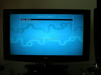
Once the USB image is burnt, it was flawless. Here are some screenshots (you are seeing my TV, as my EEEBox is connected to my TV):

Boot loader:


Boot splash screen:


From the time, I selected 'Boot Meego' at the boot loader, it did not take more than 15-18 seconds to boot and get to the Home screen. It was impressive. For a handheld, I guess this is a big plus. A quick boot and a bunch of features at the finger tip, makes sense. Unless you know it already to be a Linux variant, it is difficult to predict by its appearance.

The Home screen:


Actually once I opened a bunch of applications, this home screen has more items. It acts like a task bar to switch between various running apps. All my devices were detected and Meego had its drivers: Display, Audio, Ethernet, Wifi. The first thing I wanted was to bring it on to my Wifi network and run VNC so I can play with it remotely. My EEEBox is just a computing node with no input devices (so I had to borrow it from my desktop for a while). Setting up Wifi was easy as any other OS. It detected all the wifi networks. Key-in the password as necessary and it just connects!

Wifi Configuration:


Once connected, I was so excited to play around with the network stuff. With Google Chrome browser handy, it wasn't any different than any other OS. I wanted to try out a video from youtube, to test the graphics capabilities. I was only stunned. I even ran the video in full screen and it was hassle free. See for yourself.


I am seriously considering to use Meego when I need to use my EEEBox as a media center PC -- which is what I do most times with it connected to my TV. Primarily because it is much faster to load and light-weight. Presumably, given that it is a Linux variant, it may not be difficult to port any non-UI services to Meego (the UI framework is specific to Meego, I could see that right at first look -- in Meego terms it is called UX, User eXperience). Btw, I did install the VNC server (vino) on Meego and was able to control it from my network. There is a Linux Shell available in the menus, which is a native linux shell opening up the beast behind. 'rpm' is the package manager. It was fun!

Friday, July 31, 2009

Booting Linux live from mobile phone

== If you had landed here thinking this is about booting Linux on your mobile phone, "NO". This is about booting Linux on a comp/laptop from a mobile phone ==

The concept of booting and using Linux without having to install it on hard disk (aka Live CD) has been there for years (at least 10?). Thanks to Knoppix -- the pioneer in this approach. This later evolved to booting a live CD from media other than just CDs, like pen drives etc., With the later BIOS, supporting USB devices in the boot list, this had become pretty handy. I was a big fan of Damn Small Linux (DSL), which is really a damn small linux (with just a 50MB foot print) and goes almost invisible on your pen drive. I used to happily carry around DSL on my pen drive 2-3 years back.

But hold on. Why do I need to carry a bootable linux on my pen drive?? Anyways I need a comp to boot it; and the comp would anyway have an OS installed. Then why? True, but it is handy. I primarily see this useful for 2 purposes:

1. To use it as a recovery tool if something terribly goes wrong with my comp -- I do backup my master-boot-record (MBR) and the partition table (pretty easy to backup/restore from linux) etc., so I can recover my PC if something goes wrong at that level. This is also useful to analyze any comp for that matter if that fails to boot.

2. I can carry a set of applications along with me. If I have a comp infront of me, I would like to have a C/C++ compiler on it, maybe python interpreter and sometimes Office suite (MS office or open office). I cannot expect this everywhere I need it. Well, my own personal comp in my home town (one of the powerful ones I had during my Engineering with 64MB RAM and 500MHz processor :D) now barely has anything useful in it. It does not have most of the applications that I would need for today; and some times it does not even boot when I need it to :) No photoshop, python, games etc., Carrying a linux satisfies all (at least, most of) these requirements.

This being so useful, the major setback is the necessity to carry around that pen drive all the time; this drawback supersedes and suppresses all its advantages, and I mostly did not have my pen drive with me when I needed it ; And at some point, I forgot which of my 'n' pen-drives had the Linux live installed -- and that was the end to my use of this approach.

Recently, this thought struck my mind -- Why shouldn't I use my mobile phone as a pen drive, as I carry it all the time. And now that I have a Windows Mobile phone, I was really interested to see my "Windows" phone striving hard to help me in booting Linux on my comp :). But, I wasn't sure if that would work, without having to have a dedicated memory card. I was very clear that this is useful only if I can use the memory card for any other use on my mobile, like earlier. I tried various flavors including Fedora, DSL and Knoppix. My first choice was DSL -- it being so small, but that failed to boot off any pen drive on my laptop and my desktop (Gave up! maybe it does not support a variety of hardware?). Fedora 11 was the next choice. I used this live USB Creator, but that failed to boot too -- I didn't spend much time on it. I thought I would try out the legend Knoppix and it just worked effortlessly. The only important thing to notice in this project is, that we need to boot Linux off a FAT16 drive. The knoppix live CD comes with the isolinux boot loader that operates off an ISO -- but that wouldn't help us here. Thankfully, syslinux is a boot loader that does this job for us.

So, here is what you need to do if you need to boot Linux from your pendrive or Windows Mobile or any other mobile that supports Mass-storage mode.

On Windows: (TRY AT YOUR OWN RISK!!!)

1. Download Knoppix Live CD ISO image.
2. Download syslinux.
3. If mobile, put your Mobile in USB Mass-storage mode and connect it to your PC (else connect your pendrive to your PC).
4. Extract the Knoppix ISO to a folder say C:\MyFolder (Many software could do this including WinZip, 7Z etc.,)
5. Copy all the files from the C:\MyFolder\boot folder to C:\MyFolder\ (ie., bring the files inside boot folder to the parent directory).
6. Rename C:\MyFolder\isolinux.cfg to C:\MyFolder\syslinux.cfg (thankfully the config files are similar between isolinux and syslinux).
7. Delete the isolinux.bin file from C:\MyFolder\ (we don't need this).
8. Now copy all the files from C:\MyFolder to your mass-storage folder (say G:). Note: Directory structure should be such that all files in the C:\MyFolder should be in the root directory of your mass-storage drive.
9. IMPORTANT: Be very careful at this step. If you give a wrong drive letter, you may spoil your computer from booting. Open up a command prompt. CD to the folder where you have syslinux and run 'win32\syslinux.exe -ma G:' (I assume G: is your mass-storage drive).

You are all set. Make sure you have USB removable device / USB HDD in the boot list (with priority ahead of your HDD) of your computer. If all done well, connect your mobile/pendrive to your comp and reboot; you should see Knoppix booting off it.

Here is my Lenovo T400 Laptop booting Knoppix from my Windows Mobile ASUS P320: (The video is little long, please feel free to forward if you feel bored; but I want to provide even granular details for the interested, so didn't strip it down).


Have fun!