Showing posts with label home automation. Show all posts

Sunday, April 19, 2015

Arduino over Wifi via ESP8266 module

Arduino is pretty handy for low powered projects and is cost-effective (against Raspberry Pi). Not being able to connect to a network natively is a big challenge in applying Arduino for most use cases. While, Arduino has a Ethernet Shield for quite a while, it is impractical to expect a Ethernet port at every point an Arduino would be required. I do have Ethernet-over-Power (EoP) at home to extend its reach, but still didn't scale for me (the over all cost will also include a EoP adapter).

ESP8266 is an effective way to connect Arduino to a Wifi network. It is not a Arduino specific shield. It is a general purpose module that could be mixed with any other micro controller unit/circuit. All you need is a UART communication support on the other end (which almost all micro controllers have built-in). The added advantage is the cost, form-factor (unlike other shields) and just uses 2 pins from the Arduino (RX/TX of UART). The ESP8266 module is pretty small, but does its job well.
ESP8266 Wifi Module

Once powered appropriately, you could communicate with the ESP8266 module via serial communication (@9600 baudrate, at least my version of ESP8266). The Wifi configuration/data everything is then communicated via the extensions to a standard AT command set. This being UART based, its going to be imposing restrictions on the rate of transfer of data (but might not matter for most use-cases) -- just to highlight the difference against a USB or SoC based Wifi implementation.

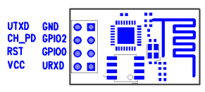
ESP8266 PinOut

The module does have a built-in TCP/IP stack, so we don't have to worry about that -- that's why we do get response to ping automatically (as shown in the video below). It is not full-fledged though; provides basic connectivity over Layer4 -- good enough. It does have its own DHCP client as well.
There is a open-source library for ESP8266 for Arduino:


This is what I used, except for few fixes that I had to do. Some of the AT commands were differently used in the library. 

Refer to ESP8266_WiFi_Module_Quick_Start_Guide for more up-to-date AT commands.

Here is the video showing my project in action :) Arduino joins my home Wifi network; shows its own IP on the LCD; runs a TCP server at port 1555 and waits to accept new connections. I connect from my desktop Ubuntu and send a message which shows up correctly on the Arduino LCD.


This is going to be a cool extension to my geyser control project now -- I should be able to control my geyser from anywhere and more importantly time it based on the needs. Some sort of security needs to be worked out.

Sunday, December 14, 2014

Home Automation: Arduino controlled Geyser

A long-pending post. I had built this project way back in May 2014, during the summer (in India). In one aspect, it seems better to have delayed this post, as my project has gone through a few bug fixes and enhancements, both in hardware & software -- so I can talk about the most recent version.

I had done a few other home automation stuff earlier like this one : DIY: Raspberry Pi controlled Power Strip - Part 1. I was/am constantly on the look out for any opportunity to automate things at home. We have been wasting lots of energy, as our geyser almost runs till cut-off most of the times and we won't need so much hot water during summer. This was simply because we won't remember to turn it off on time. I wanted to fix this by building a timer controlled switch for the geyser using Arduino.

I had earlier used Raspberry Pi for home automation. This time, I wanted to use Arduino for a few reasons. Unlike the power strip, which is completely network-controlled, this is a low power project and doesn't necessarily be network-controlled (I could actually snap in a Ethernet Shield for Arduino and make this network-controllable -- remember, I have Ethernet running over my power lines anyway, so easy to get a network anywhere). I also wanted to explore Arduino as part of this, as Arduino is relatively low cost and very low power (< 1W). I buy Arduino/Raspberry Pi from Ebay India directly (though they could be cheaper by other channels).

Here is the circuit:

This circuit was drawn using some online tool (that isn't perfect). The tool had bugs, so some of it didn't come out the way I want. Still conveys the idea.

The project is primarily, a relay (Relay2) driving the high power geyser (ours is around 2500W). The original plan was to drive this relay by a signal from Arduino. The high power relay that I procured, required a signal voltage of around 9V without which it couldn't really turn on the load. Arduino GPIO pins operate only at 5V. So I had to introduce another relay (Relay1) to supply the required 9V (external source), but on signal from Arduino. This also ensures, not much current is drawn directly from Arduino. Arduino Uno has a built-in voltage regulator (safe up to 12V), but I decided to be safe and use a custom voltage regulator using LM7805 (I wouldn't want to heat up Arduino or burn it -- lot cheaper to build an external voltage regulator - around Rs.70). I also have a 16x2 LCD to display the status/timer (see photos). The LCD is driven using the standard Arduino LCD library.

Here is the voltage regulator (built separately and tested out):


It doesn't turn on the geyser instantly. It runs a 10 second timer before it turns it on. This is to ensure that any electricity interruptions don't turn on/off the geyser too quickly. Better for the geyser.


Showing the countdown to shutdown:


The project in action (for the last 6 months). The USB cable connects to the data port of Arduino via a hole in the case -- this is used for software upgrades in-place; just connect my Mac and click on a button to flash it instantly with new code. eg., Once the winter started, I had to patch it to increase the timer a bit to get it to the right temperature.


This board is in series with the geyser, so turning on the physical switch doesn't turn on the geyser (expected).

Saturday, April 13, 2013

DIY: Raspberry Pi controlled Power Strip - Part 1

This post will cover some behind-the-scene details on what went behind making this power strip. Had been quite busy for a while, so couldn't make it earlier.

There were few questions that I had to answer before I was sure I could build this:
  1. How do I control 220V AC from an electronic circuit, safely? Can I do it right the first time so I don't blow up the raspberry Pi? Being completely a software guy, this was a challenge. This was the first part of the problem I solved as shown in my earlier post on Controlling 220v Bulb using Raspberry Pi.
  2. Can I fit this whole solution seamlessly into an existing power strip so it has a clean form-factor and intuitive to use? Finding one such power strip which had enough space to hold additional circuits was a challenge.
  3. Building software so I can remotely control the power strip over any device. I decided to go the web interface route, so I can do it easily from any device. The software I eventually implemented is based on RESTful APIs, so it would also be easier for me to write an Android app or any other app over this interface.

Controlling 220V AC from Raspberry Pi


One of the foremost requirements for choosing Raspberry Pi was that it has programmable GPIO (General Purpose Input / Output) headers, without which any electronic interfacing would be pretty difficult and inefficient. Most micro-controllers (including modern microprocessors do provide GPIO pins) for interfacing with other low-level hardware peripherals. The voltage on a GPIO PIN can be controlled by instructing the micro-controller. Usually a TTL low/high is used to signal 0 or 1. But it is totally up to the interface to decide how to interpret it. Raspberry Pi uses 3V3 TTL, which means a 3.3V for high and 0V for low. Specially when you are using the GPIO pins for input, make sure the voltage doesn't exceed 3.3V. For the power strip, it is only in output mode.

Relay is another important component. It is an electro-magnetic switch that is used to turn on or off the high voltage. Relays require slightly higher voltages (>=12V) to work. When there is enough current flow, an electro-magnetic coil gets magnetized and pulls off a lever to turn on the switch. When the power is switched off, there is no magnetic field, and a mechanical spring pulls it back to its original position. Relay is a mechanical device and might suffer some latency and noise during its operation. It is not meant for high-precision control, but in my case this is good enough.

Since relays work on higher voltages and that it requires substantial current, a relay cannot be driven directly from a Raspberry Pi. It is very common to use a transistor as a switching device to turn on slightly higher voltages and/or when you need more current. This allows us to withdraw very less current (only the base current) from the controlling source (in our case Raspberry Pi) and to use a completely different power source (>=12V) for the controlled device (in our case, a relay). I have plugged in a 12V power adaptor which provides sufficient current to turn on/off the relay.

This is the circuit that drives a single relay: (The core idea of this circuit is a very common circuit that is used to control a relay via a transistor. I have customized it to appeal for the given use case.)


Remember that Raspberry Pi runs off USB power. Model B has a cap of 700mA in the inlet and this current is used for the complete functioning of Raspberry Pi. Any current that we draw out of this, is expensive and we need to be cautious. Specially if you are planning to drive a load (say a LED) directly, without using a different power source. 

WARNING: As I learned, there is no fuse of any sort behind the GPIO headers -- so any incorrect use might blow the micro-controller, thereby making a Raspberry Pi brick. Take extreme precautions and ensure that you are fine with the current you draw/sink from/into the GPIO.

The GPIO18 is just one of the many GPIO pins that could drive this transistor. To turn it on, my code will set a HIGH on that pin, thereby raising the voltage on that pin to 3.3V. With the required V-BE (the base-emitter voltage) at 0.7V to turn on, for the 4.7KOhm base resistor, the transistor will just draw around 0.5mA current from the raspberry Pi. Even when multiple relays are ON, there is no risk of over-drawing current from Raspberry Pi. The Diode D1 provides protection against any reverse current that could occur at the moment the relay is switched off.

Raspberry Pi has a GPIO python library that we can use to control the GPIO pins with ease. By being able to control from python, I didn't have to go through the pain of cross-compiling every time I modified any code.

Snip of code:
#
#initialization
#
import RPi.GPIO as GPIO
GPIO.setmode(GPIO.BCM) # use BCM pin numbering
GPIO.setup(gpio_pin_number, GPIO.OUT) # mark for output

#end of initialization; following could be called multiple times.

GPIO.output(gpio_pin_number, GPIO.HIGH) # output high / 3.3v
GPIO.output(gpio_pin_number, GPIO.LOW) # output low / 0v
#
As simple as that. Based on the command issued remotely, my power strip daemon would choose the right gpio_pin_number and set it to HIGH or LOW appropriately.

This post is getting long :). So, more about the packaging of the relay board, associated software design, in the subsequent posts.