Monday, March 30, 2009

Digital Thermometer

This is where I was heading to. With the last module, I was ready with 2 digit 7segment LED which could be used to show the current ambient temperature.

The only remaining part is to integrate the temperature sensor into the system, read, decode, and display the reading. I used the LM35 temperature sensor which is quite simple and handy to use (at the size of a transistor). LM35 is a centigrade temperature sensor and has 3 terminals -- VCC, Vout and GND. Connect VCC and GND with a 5V across, and you can calculate the current ambient temperature based on the potential available at Vout. Based on the datasheet of LM35, Vout is set to (0mV + 10 mV/degree). So a 100mV at Vout means a 10 degree centigrade temperature sensed.

Now, the remaining task is to make the micro controller (I use ATMega8) read this reading. uC deals only with digital data. This being an analog data, it has to ideally be fed through a Analog-to-Digital-Convertor (ADC). Incidentially, ATMega8 has an inbuilt ADC (with 6 channels in PDIP package). For the ADC to decode the analog data properly, the ARef (Pin 21 in PDIP) terminal has to be set to a reference voltage. To give an example, if the reference voltage is 5V, one unit in a 10bit ADC is defined as (5/1024) volt ie., ~5mV. So for every 5mV from the analog input (in our case, LM35), the reading from ADC goes up by 1 unit.

In my case, the ARef is set to 4.85V. Hence one ADC unit is (4.85/1024) volt ie., 4.736 mV. As discussed earlier LM35 outputs 10mV per degree Centigrade; so my temperature reading is (adc_reading * 4.736 / 10) or (adc_reading * 0.4736) deg. Centigrade.

Hardware:
The hardware part is just connecting the LM35 to my previous module. The output of LM35 is connected to ADC channel-2 (PIN 25 in PDIP) -- as channel 0,1 are shared with PORTC's 0-1 bits which I have been using as control bits for selecting the 7segment digit in TDM mode.

Software:
After enabling ADC channel-2, the ADC's current value is read and the temperature is calculated using the above derived formula. The value is stored in a global volatile variable which is displayed in the 7segs as in my previous module. The temperature is read every 2 seconds (just arbitrary).

Here is the code:

// Author : Gerald Naveen A (ageraldnaveen at gmail dot com)

#include <avr/io.h>
#include <avr/interrupt.h>

#define F_CPU 1000000

#include <util/delay.h>

static volatile uint16_t g_temp_c = 99;

// insert TDM based seven segment code here... interrupt handling etc.,
// didn't want to bloat the codespace while publishing.

void initialize_adc()
{
ADMUX = (1 << REFS0);
ADCSRA = (1 << ADEN) | 7; // enable && prescaler /128
}

uint16_t read_adc_channel(unsigned int ch)
{
uint16_t result;

ADMUX |= (ch & 0x07); // enable ADC channel 7

ADCSRA |= (1 << ADSC); // start conversion

while(!(ADCSRA & (1 << ADIF))); // wait for conversion to complete

result = ADC; // read the result

ADCSRA |= (1 << ADIF); // signal done to ADC

return result;
}

int main()
{
sei();

initialize_adc();
// initialize timer etc., as my previous module

while(1) {
// reading from channel 2
uint16_t val = (uint16_t) read_adc_channel(2) * 0.4736;
if(val < 100) // just to avoid noise, have a upper limit (100 too big?)
g_temp_c = val; // send it for display

_delay_ms(2000);
}
return 0;
}
Here is a snapshot of my setup showing the temperature inside my refrigerator :) I could not shoot a meaningful video, as the project shows an almost constant number. The temperature was actually showing 8 degrees when I opened the fridge after putting my project inside for around 5 minutes; when I opened the door and while I was trying to place the breadboard upright for the digits to be visible and clicked, the temperature had shot up by a few degrees due to the door being open :D


We Must Be Silent

Courtesy: Pravs World

Before we can lead, we must serve.

Before we can serve, we must prepare.

Before we can prepare, we must learn.

Before we can learn, we must listen.

Before we can listen, we must be silent.

Sunday, March 29, 2009

So Live Today!

Courtesy: Pravs World

There are two eternities
that can really break you down.

Yesterday and Tomorrow.
One is gone and the other doesn’t exist.
So Live Today!

Friday, March 27, 2009

Multiplexing two 7segment LEDs

This is a follow up on my previous post on 7segment LED display.

When it comes to displaying 2 digits, there are at least 2 choices. The simplest choice is: In addition to the existing 7bits for the first digit, add 7 more data bits and let them drive the second digit. The obvious drawback with this approach is the need for large number of data lines. With increase in the number of digits, you need 7bits for each additional digit. At some point the idea does not scale and goes impractical.

The second choice is to use Time Division Multiplexing (TDM). In this approach the same data bus (7bit always) is used to show the digits across all the 7segment LEDs. A separate control signal is added (1 bit per digit -- simple appraoch; ideally 'log (base 2) n' control lines are enough for n digits). The control signal is used as 'chip-select' to select the appropriate digit and the data at the data bus at that moment is used to light up that segment appropriately. An important caveat in TDM is that, the 7Seg LEDs will not retain the digit when the control transfers to the next segment (obvious?). As a result only one 7seg will be lit at any point in time. Thanks to the persistence-of-vision property of the human eye, by switching the control between the LEDs at a fast pace, it is possible to "virtually" light up more than one 7seg at the same time. And that's the idea behind this project.

Hardware:
The 7bit data bus control the digit to be displayed (as in my previous post with single 7seg). Additionally, 2 control lines, each connected to the common anode of each of the 7seg select the digits by supplying the positive voltage(+5V). It is actually a good idea to connect the control signals to the base of a transistor and use the transistor as a switching device to turn on/off the positive voltage to the LED -- I don't have transistor at the moment; given that the 7seg does not draw too much current, it was safe to drive them directly from the uC's output pins. I would not recommend this though.

Software:
The software part is little complicated. The idea of the program is to display 2 digits of a running counter. The counter has to be incremented at a slow pace (once per second?) so human eye can follow the counter. However, the 7segs have to be refreshed at a very high rate otherwise we would see flickering of digits (remember only one of them is lit at any moment). To implement this, it is possible to run a loop with few ms sleep interval and keep refreshing the digits; and increment the counter only after every 100 iterations (so in effect the counter is incremented only after a second or so). This is naive and may not scale when there is more functionality than just incrementing the counter. So the ideal method is to make use of timer interrupts. ATMega8 has 3 timers. I have made use of timer0. Once enabled, whenever the counter belonging to the timer (in this case TCNT0) overflows beyond its size (in this case 8 bit), the uC invokes the appropriate interrupt handler. In the interrupt handler, I've written code to update one digit at every invocation.

Here is the code:

/* Author: Gerald Naveen A (ageraldnaveen at gmail dot com) */

// Write the digit on PORTD (0-7 bits)
// Select the digit on PORTC (0-1 bits)
#include <avr/io.h>
#include <avr/interrupt.h>

#define F_CPU 1000000 // 1MHz
#include <util/delay.h>

//my implementation that wraps writing a digit to 7seg
//implements seg7_write_digit
#include <gerald/7seg.h>

// volatile makes sense
volatile int g_cur_val = 0;

void initialize_timer0()
{
TCCR0 |= (1 << CS01); // configure the prescaler for timer0
TIMSK |= (1 << TOIE0); // enable timer0 interrupt
TCNT0 = 0; // initialize timer0 counter to 0
}

// the TIMER0 overflow interrupt handler
ISR(TIMER0_OVF_vect)
{
static int n = 0; // decides which digit to update now.

if(!n) {
// make sure you disable the control signal before changing
// the data bits. otherwise you can notice small leakage of
// data onto other digit.
PORTC = 0;
seg7_write_digit(g_cur_val % 10); // output ones
PORTC = 0x1;
}
else {
PORTC = 0;
seg7_write_digit((g_cur_val/10) % 10); // output tens
PORTC = 0x2;
}
n = !n; // toggle the digit selection
}

int main()
{
DDRD = 0x7F;
DDRC = 0x03;
PORTD = 0xFF;
PORTC = 0; // disable control signals by default

sei(); // enable global interrupts

initialize_timer0();

while(1)
{
g_cur_val++; // just keep incrementing the counter
_delay_ms(100);
}
return 0;
}
Here is the project in action:


Monday, March 23, 2009

7Segment LED Display

After getting the micro controller (uC) work, now it is time to start building small modules for later use in bigger projects. 7Segment LED is one of the common ways of output when the data is numerical.

I have a common anode 7Segment LED (Red). The 7Seg has seven segments each having to be separately lit up by grounding the appropriate cathode for that segment (actually not necessarily ground, any potential lesser than anode by ~1.5-5V). So, to control 7 segments (using a simple enough circuit), we need to have 7 bits of info, each driving one segment. As the segments are controlled through the cathode, the uC has to sink current from the 7Seg to light up a segment. This is achieved by outputting a logical 0 at the corresponding bit in the uC's output port.

The ideal thing is to connect each of those 7 cathodes to their corresponding output pins through a current limiting resistor of 330ohms. For ease of use and testing, I've positioned the resistor between the 5V supply and the anode. This is much simpler for the proof of concept and easy to wire on the breadboard. The drawback of this approach however is that, the current gets split into each of the lit segments, as a result the brightness of the segments vary based on the number of segments lit (1 being the brightest and 8 being the dimmest). I don't really care at this moment, given that I know the reason.

That's all the about the hardware side. The software needs to output the correct bits at the output port to display a digit on the 7Seg. Each digit is displayed by lighting 2 or more segments in the 7Seg. I've created a static mapping between the digits (0-9) and their corresponding segments-to-be-lit. Now, based on the number to be shown, the software outputs the bits and the digits appear on the 7seg. To keep it appealing, I've made the program to display the last digit of a running counter (as usual, a sleep between the increments to keep it visible to the eye).

Here is the code:

/* Author: Gerald Naveen A (ageraldnaveen at gmail dot com) */

#include <avr/io.h>

#define F_CPU 1000000 // 1MHz
#include <util/delay.h>
#define G_SEGA (1 << 0)
#define G_SEGB (1 << 1)
#define G_SEGC (1 << 2)
#define G_SEGD (1 << 3)
#define G_SEGE (1 << 4)
#define G_SEGF (1 << 5)
#define G_SEGG (1 << 6)

uint8_t seg7_map[10]= {
G_SEGA | G_SEGB | G_SEGC | G_SEGD | G_SEGE | G_SEGF, // 0
G_SEGB | G_SEGC, // 1
G_SEGA | G_SEGB | G_SEGG | G_SEGE | G_SEGD, // 2
G_SEGA | G_SEGB | G_SEGG | G_SEGC | G_SEGD, // 3
G_SEGF | G_SEGG | G_SEGB | G_SEGC, // 4
G_SEGA | G_SEGF | G_SEGG | G_SEGC | G_SEGD, // 5
G_SEGA | G_SEGF | G_SEGG | G_SEGC | G_SEGD | G_SEGE, // 6
G_SEGA | G_SEGB | G_SEGC, // 7
G_SEGA | G_SEGB | G_SEGC | G_SEGD | G_SEGE | G_SEGF | G_SEGG, // 8
G_SEGA | G_SEGB | G_SEGC | G_SEGD | G_SEGF | G_SEGG // 9
};

void seg7_write_digit(uint8_t d)
{
if(d > 9)
d = d % 10;

PORTD = 0xFF ^ (seg7_map[d] & 0xFF); // output logical 0 to light that segment
}

int main()
{
DDRD = 0xFF;
int i = 0;
while(1)
{
seg7_write_digit(i++);
_delay_ms(400);
}
return 0;
}
Here is the circuit in action:


This code I wrote is useful to drive one 7Seg LED; the next job is to drive more than one 7Seg LED -- yes it is different. See you then.

Saturday, March 21, 2009

Hello AVR!

Finally, my first AVR micro-controller based project is ON! I always had a great passion for embedded electronics, but never had a chance and guidance to improve. This is a first step towards that -- thanks to the Internet for a handful of articles.

After a week's struggle to setup the whole environment, I managed to successfully flash my first program into my ATMega8 micro-controller and use it to drive 2 LEDs. The power of the ATMega8 is just amazing; with very little power consumption, the features it provides for embedded applications is just too good (In a 28pin PDIP packaging, it has around 23 I/O pins, 6 channel ADC, Pulse Width Modulation, Programmable USART, ISP, 3 Timers and clocking at 8-16MHz).

Why the struggle:

This shouldn't have been a struggle, if I wasn't unlucky to get a faulty ATMega8. This is my first AVR project and I had bought tonnes of electronic goods starting from multimeter, soldering iron to AVR ISP programmer, ATMega8, crystals, resistors, capacitors, inductors, LEDs....(I've actually bought more stuff which I'm yet to use). After setting up the circuit as required, connecting the micro controller (uC) to the ISP programmer and the programmer to the computer, I was not able to flash my controller at all and that was the problem :( I struggled struggled and struggled to debug every portion of this chain; tried a different ISP programmer (built my own serial ISP programmer) but no use; after achieving no success, the final and the only option was to suspect my ATMega8 uC -- the hero of this project. Anyone would think why it took me so long to suspect this; True. But I did suspect this earlier, however I wished this wasn't the issue because I didn't have a spare one with me and I cannot get this in the nearby electronics shops. Finally I had to personally go to SP road in Bangalore (Bangalore's version of the Chennai's ritchie street) and get a ATMega8. Sigh!!! All said and done, it is finally working :D

This is pretty much a 'Hello World' nothing else. The uC just drives the 2 LEDs I have connected over PORTC through the 330ohm current limiting resistors. To keep it a bit fancy, I made the 2 LEDs to represent the last 2 bits of a running integer counter. So basically the LEDs glow in the following pattern as the integer keeps incrementing -- 00, 01, 10, 11. A 500ms delay between the increments, to keep it visible to the eye.

The code would look something like this (I use the WinAVR cross compiler).

#include <avr/io.h>
#include <util/delay.h>

int main()
{
DDRC = 0xFF; // Enable output on PORT C
uint8_t c = 1;
while(1) {
PORTC = c++; // output the integer on PORT C, whose 0-1bits drive the LEDs
_delay_ms(500);
}
return 0;
}
Here is the Hello AVR! in action:


Friday, March 20, 2009

New forms of telemarketing

Thanks to the NDNC (National Do Not Call registry) in India that the telemarketing's nuisance has become really tolerable. There have been days where I would come out of a meeting just to attend a call from an automatic advertisement system. These days I hardly get any message/calls. Great move! This isn't the news, but...

I am starting to realize 2 new trends in telemarketing to get away with the NDNC regulation.

1. When I call the service provider (bank, phone etc.,) for some query, they make sure they advertise at least one product to me. They make use of the customers like me who wouldn't just disconnect the call once the query is answered, but would finish the call completely (including a 'same to you' for a 'have a nice day' from the executive). One good thing about this approach is that, they have become much more pleasing than before -- that's the way to make you listen to their advertisement at the end. That's technically not violating NDNC!!

2. First one is rather acceptable; as this happens only when "I" call them up. The second type is totally ridiculous. These people create a website (or a page in their existing website) to ask them to call us for more info. These days I see a number of websites which have the option of 'Register for a callback for more info' kinds. As earlier, the companies get hold of a database of phone numbers and names. I "guess" that they also have a separate team which would just generate fake requests at the website with those info from their database. Now they are free to call us, claiming that we asked for the call. To make it so formal and legal, they also send an automated SMS which says something like 'Recently you had asked for more info on xxx. Thanks for your interst in xxx. Within 24 hours, our service representative will call you back'. Clever??!! I really got pissed off when I got such a message last week and without surprise they also called me the next day. I finally confirmed from him that the case was registered with a wrong email id but with correct name and mobile number. When I claimed that I never raised any request, he didn't seem surprised; but was rather more interested in still explaining me the product -- this says it all, that it is a practice, not an accident. He claims it coolly that any of my relatives could have registered for me -- I could only LOL!!!

Wednesday, March 11, 2009

Capturing an image from a webcam using Python

It is amazingly simple to do this. All you need is the VideoCapture library for python and Python Imaging Library (PIL).

The VideoCapture library wraps the interactions between Python and the webcam or any other camera (not sure if this works against other imaging devices like scanners). It is a very simple-to-use library. You can download the VideoCapture library from here.

Python Imaging Library (PIL) is the standard python library for image manipulations. The VideoCapture library returns the captured image as an Image object as represented by PIL so it can be used across many other modules of python just like any other image. Download PIL here.

The following is a simple example app. It captures an image from the webcam and converts it into grayscale and shows it to the user.

import VideoCapture as VC
from PIL import Image
from PIL import ImageOps
import time

def capture_image():
cam = VC.Device() # initialize the webcam
img = cam.getImage() # in my testing the first getImage stays black.
time.sleep(1) # give sometime for the device to come up
img = cam.getImage() # capture the current image
del cam # no longer need the cam. uninitialize
return img

if __name__=="__main__":
img = capture_image()

# use ImageOps to convert to grayscale.
# show() saves the image to disk and opens the image.
# you can also take a look at Image.save() method to write image to disk.
ImageOps.grayscale(img).show()

Simple, isn't it?

Monday, March 09, 2009

The Crisis of Credit Visualized

Just came across an excellent video explaining the credit crunch.


The Crisis of Credit Visualized from Jonathan Jarvis on Vimeo.

Sunday, March 08, 2009

Using Vodafone Live! on your computer

=== The specific services I talk about here, are applicable only to India; but the concepts apply to anywhere in the world ===

This post is the continuation of my previous post on sharing your mobile's GPRS/EDGE connection on a computer.

Vodafone Live! and other similar services (Airtel Live!?) do not allow the use of the mobile's internet service on a computer. Generally these types of services are called as WAP Internet package (or something similar, but with a WAP tag in there description).

There are two restrictions that are common here:

1. They cannot reach any of the Internet servers "directly". ie., you need to always connect through a proxy server which supports most common protocols. This provides the service provider an easier management to restrict the users from accessing certain services that are not allowed under this package (something like VoIP?)

Solution: This is a straight-forward solution. Once you share the connection with your computer as I explained in my earlier post, you need to configure your browser to use your service-provider's proxy server at the right port (you should have used this info already to configure Internet connection in your mobile phone). You can try ping'ing the proxy server from a command prompt on your computer and you should see replies. You can also notice clearly that you will not be able to ping any other webservers/public IP other than your service provider's proxy server -- clearly indicating the idea behind the use of proxy server.

2. They do not allow any device other than a mobile to use the Internet service. This infact is difficult to ascertain. This is because of the lack of support in the underlying protocols. Most protocols do not carry (actually they aren't meant to) the user related information. The only information that the service provider is able to rely on is the user-agent attribute in the HTTP header in every HTTP request. The idea behind this attribute was to allow the webservers to format the output based on the user's device profile so it can fit well on the user's device. Generally the user-agent information carries the browser's name, operating system information. Given that most of our requests are going to be HTTP(S) based (while browsing), this is enough for the service provider to restrict the use of internet on the computer.

Solution: With a few experiments with wget, I could figure out that the user-agent indeed was used to restrict the usage. wget was able to retrieve the pages successfully on my computer while sharing my Vodafone Live! connection from my mobile. With wget configured to use the user-agent as-is that firefox 3.0 uses, I could get 'access denied' even when requested from wget. After playing around a while with various user-agents I finally figured out that it was indeed the OS part of the user-agent that they care and not the browser itself. Even though Firefox 3.0 does not exist on a mobile platform (yet!), they do allow the use of firefox 3.0 in the user-agent if I make sure I tweak the OS part of it. That having proven the concept now, how do we make the browsers work with the phone; after all wget cannot be used to browse. Thankfully, the great Firefox supports a config variable that allows the user to override the user-agent (I'm not sure about other browsers; I'm fairly confident MS Internet Explorer does not support). To configure, just type 'about:config' in the firefox browser URL and add a new String config variable with the name 'general.useragent.override' (this does not exist already) and set its value to whatever you want (basically it should be devoid of Windows NT etc.,) and you are all set. Just start browsing (don't forget to set your proxy server appropriately if required).

It should look something like this:


I would suggset not to leave the user-agent with an arbitrary value all the time. When you are not accessing Internet over your phone, delete (Reset) that config variable so that the actual user-agent is sent.

Thursday, March 05, 2009

Using mobile's GPRS/EDGE for Internet connectivity on computer

GPRS/EDGE services provide internet access to mobile handsets. The services have become readily available and are very economical that many people have started using GPRS/EDGE on their mobile phones. I have it for atleast 3-4 years now in India and I find it really useful specially while travelling when you need frequent access to data and might not be connected to Internet otherwise. I use it to read news and check emails specially and even to track the train's timings and current status as I wait for the train in the junction -- believe me it is handy.

To add to its existing benefits, wouldn't it be wonderful if one can connect to Internet on a desktop/laptop PC using the mobile phone's GPRS/EDGE service? And yes it is possible.

Technically there are 2 possible ways to do this:

1. Connecting to Internet using the mobile as a GSM modem; so one can just dial in to their network service -- the dial up networking service (DUN). This method has been very common and almost all decently higher end phones support an interface for GSM modem. On installing the correct drivers on the computer, the mobile when connected over (usually) USB will be recognized as a USB based modem which can be used to dial in. Obviously, this requires support from the mobile service provider. Many service providers (including Airtel, Vodafone) do support this option but usually are costly and not worth it if you aren't roaming a lot. (eg., paying a monthly rental of Rs.200 on a data plan but using it once a month is not worth the money). But remember this is the easiest and widely available means to connect.

2. The computer connects to your mobile phone and establishes a personal area network (PAN) between them. This network shall be established in any means that you have -- maybe a USB Lan over USB, or a Bluetooth PAN over bluetooth. Once the network is established, if the phone can route the traffic to/from the computer to the EDGE, you have an Internet connection on your computer. At application level, if you can manage to run a HTTP proxy server (you can even write your own) on your phone that can work over the EDGE on the other side, it should do. You can configure the browser on the computer to use the phone as the proxy server. The other best option is : if the OS on the phone supports to make the phone as a full fledged router to route the data between your EDGE network and the computer. Unfortunately this option is pretty difficult to customize yourself if the phone does not support it -- as it needs support at the OS level.

Now, Windows Mobile (and Windows OS) users take a deep breath; we are saved. Fortunately Microsoft has implemented the 'Internet sharing' functionality into Windows Mobile (I guess 5.0 and above) which allows us to do exactly the same thing (with a Windows computer). The interface is very simple and is much easier to use than even the GSM modem counterpart.

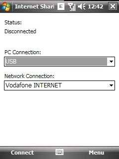
On your WinMo phone, just click on Start->Programs->Internet Sharing. The following (or similar) window would popup.


Now select the mode of connection you want to connect through. USB connectivity is easier if you do not know how to connect over Bluetooth PAN. Connect your Windows Mobile mobile onto your computer through an USB cable (I assume the standard setup to communicate over ActiveSync is installed on the computer). On the Internet Sharing dialog on your mobile, just select USB and the appropriate service connection point that you have configured on your mobile. Click Connect. The mobile registers itself with the computer as a 'Windows Mobile based Internet Connection sharing device' and a virtual network adaptor gets installed. Then it also creates a Network connection that connects automatically to your Windows mobile over DHCP and acquires an IP address to talk over. You should be able to see the new connection in your Network Connections dialog (Start -> Control Panel -> Network Connections) with the status as 'Connected'. In addition, you can also run ipconfig to see the new connection's IP address etc., That's it. Now you are all set to browse the Internet using your computer. Just open up a browser and start browsing.

Caveats:
1. If you are using Vodafone Live (or a similar variant from any other service provider who restricts the use only to mobiles), every thing will go through as explained, except that your browser would not be able retrieve any data or would always show '403 Forbidden'. It is possible to work around this, you might have to wait for my next post on this. I do this.

2. Incase your computer is connected over ethernet/wifi to your local network which has a default gateway configured, you might have to tweak your routing table to redirect the Internet traffic to your mobile phone.

Wednesday, March 04, 2009

Flexible touch-screen displays

After flexible displays, it is now flexible touch-screen displays. Only drawback I see is that they use a inductive screen for touch sensitivity -- thus requires a special magnetic stylus to make it work (but probably a fair restriction on a flexible display, after all a flexible screen might get in contact with so many unintentional objects). Just a proof of concept but a big step forward!!

Monday, March 02, 2009

My pencil arts - #4 - Lady

First 2 are photographed and the last one is scanned copy.


An interesting spam and analysis

I just noticed an interesting spam mail into my mailbox recently. Unlike other spams this mail had a different intent (read it to know). No product marketing, no wealth transfer etc., no phishing intention. The only justification I can think of was to get in touch and create a friendship and then collect the necessary info. Anyways here is the mail (as-is):

======================================================
Hello Dear,

how are you today I hope that every things is ok with you as it is my great pleassure to contact you in having communication with you starting from today, please i wish you will have the desire with me so that we can get to know each other better and see what happened in future.

I will be very happy if you can write me through this mail for easiest communication and to know all about each other, and also give you my pictures and details about me, i will be waiting to hear from you as i wish you all the best for your day.

your new friend.
Miss. Aminata.
======================================================

I was curious to just figure out if this is not a possible spam from any of my friends. I wanted to take it forward and reply if I had suspected any of my friends for this, but unfortunately it was not. The mail's SMTP header was as follows:

From Aminata Sankoh Thu Feb 26 15:47:48 2009
Return-Path:
Authentication-Results: mta209.mail.re4.yahoo.com from=yahoo.co.th; domainkeys=pass (ok); from=yahoo.co.th; dkim=neutral (no sig)
== strip little ==
Received: from [124.108.114.83] by t2.bullet.mail.sg1.yahoo.com with NNFMP; 27 Feb 2009 01:34:30 -0000
Received: from [127.0.0.1] by omp103.mail.sg1.yahoo.com with NNFMP; 27 Feb 2009 01:34:30 -0000
Received: (qmail 47623 invoked by uid 60001); 26 Feb 2009 23:47:48 -0000
DomainKey-Signature: a=rsa-sha1; q=dns; c=nofws;
s=s1024; d=yahoo.co.th;
h=Received:Date:From:Reply-To:Subject:To:MIME-Version:Content-Type:Content-Transfer-Encoding:Message-ID;
b=6DW+LjgIGtkj1fBUv41AyHZOGKeVZljOv8/lXgJLCNujOTjsjqX+R3yacDOW9Q080JdDCUuW+yBnhwnbUEpBFmILXgS2JDP6H4lVIqtCcuZ9WOgVok/2lLLwQ3ZP585/JAanJUjrOGzEBoeo8biUWzqLKHqNht4rlW7Lks12pOw=;
Received: from [41.208.161.138] by web76716.mail.sg1.yahoo.com via HTTP; Fri, 27 Feb 2009 06:47:48 ICT
Date: Fri, 27 Feb 2009 06:47:48 +0700 (ICT)
From: Aminata Sankoh
Reply-To: amina_luv8@yahoo.com
Subject: Hello Dear
To: aminsankoh@yahoo.co.th
MIME-Version: 1.0
Content-Type: multipart/alternative; boundary="0-1397759359-1235692068=:47230"
Content-Transfer-Encoding: 8bit
Message-ID: <445714.47230.qm@web76716.mail.sg1.yahoo.com>
Content-Length: 2417

== end-of-headers ==

There are few interesting things to be noticed:
  • Server authentication through domainkeys passed. So this email has been sent by the given email address from yahoo.co.th. That makes it easier to track further.
  • This email has been sent from IP address 41.208.161.138. A simple search and this IP address belongs to country Senegal in Africa -- oh ok that throws my friends out of the list.
  • The email has been addressed to the sender's address and all those bunch of people targeted are in BCC probably.
Few things which aren't clearly justified:
  • The relevant yahoo webserver (web76716.mail.sg1.yahoo.com) seems to be located geographically in Singapore. Possibly because the yahoo mail's domain was co.th (not sure if yahoo has a separate server for Thailand; maybe it wasn't available at the time of creation of the yahoo account - never mind). Maybe the user from Africa wanted to pretend to be in Thailand.
  • The reply-to address points to another email id in the yahoo.com domain. Maybe she/he sends multiple emails from different different email accounts and want to easily catch hold of the bakara(s) who replies, by diverting all the replies to one email box -- so just check one mailbox for replies?? possible.
Obviously I chose not to reply. Just beware of such mails.