Thursday, December 13, 2012

WDTV Live -- Firmware Hacking Series -- Part 3

Patching custom rootfs onto existing firmware


Once you have the serial cable built as mentioned in my previous post, it is possible to patch the current firmware installation with custom rootfs, without having to upgrade/reinstall the whole firmware with custom one.

These are the high-level steps that we need to do:
  1. Discover the partition table and identify where the rootfs is stored in the flash storage.
  2. Read the rootfs of the current firmware and push it to a different machine.
  3. Modify the rootfs to your needs, on the other machine.
  4. Upload it back to WDTV and write the flash partition appropriately.

Discovering the rootfs partition

~ # mount
rootfs on / type rootfs (rw)
proc on /proc type proc (rw)
sysfs on /sys type sysfs (rw)
/dev/sigmblockh on / type cramfs (ro)
none on /proc type proc (rw)
sysfs on /sys type sysfs (rw)
usb on /proc/bus/usb type usbfs (rw)
mdev on /dev type tmpfs (rw)
devpts on /dev/pts type devpts (rw)
none on /tmp type tmpfs (rw)
/dev/loop0 on /tmp/static_config type minix (rw)

Note the highlighted line. /dev/sigmblockh device is the one mounted as / partition. To confirm print the first 100 bytes on the device and you could notice the CRAMFS header.

~ # hexdump -c -n 100 /dev/sigmblockh

0000000   E   = 315   (  \0   @ 021 003 003  \0  \0  \0  \0  \0  \0  \0
0000010   C   o   m   p   r   e   s   s   e   d       R   O   M   F   S
0000020 234 333 016 324  \0  \0  \0  \0   k   &  \0  \0 313 016  \0  \0
0000030   C   o   m   p   r   e   s   s   e   d  \0  \0  \0  \0  \0  \0
0000040 355   A 354 003   D 001  \0   d 300 004  \0  \0 355   A 354 003
0000050 354  \v  \0   d 001 031  \0  \0   b   i   n  \0 377 241 354 003
0000060  \t  \0  \0   d                                                
0000064
~ # 
We still need to know the exact flash disk and the partition to which this device points to.

~ # ls /dev/sigm* -l
brw-rw----    1 root     root     254,   0 Jan  1  2000 /dev/sigmblocka
brw-rw----    1 root     root     254,   1 Jan  1  2000 /dev/sigmblockb
brw-rw----    1 root     root     254,   2 Jan  1  2000 /dev/sigmblockc
brw-rw----    1 root     root     254,   3 Jan  1  2000 /dev/sigmblockd
brw-rw----    1 root     root     254,   4 Jan  1  2000 /dev/sigmblocke
brw-rw----    1 root     root     254,   5 Jan  1  2000 /dev/sigmblockf
brw-rw----    1 root     root     254,   6 Jan  1  2000 /dev/sigmblockg
brw-rw----    1 root     root     254,   7 Jan  1  2000 /dev/sigmblockh
brw-rw----    1 root     root     254,   8 Jan  1  2000 /dev/sigmblocki
brw-rw----    1 root     root     254,   9 Jan  1  2000 /dev/sigmblockj
brw-rw----    1 root     root     254,  10 Jan  1  2000 /dev/sigmblockk
brw-rw----    1 root     root     254,  11 Jan  1  2000 /dev/sigmblockl

The highlighted line shows the major, minor numbers for this device. As you might know, the minor number is the partition number on the disk. In this case, the rootfs is stored in the 7th partition.

To understand where is the 7th partition stored in the flash disk, we need to know the partition information of the internal flash disk. This could be obtained in two different ways. Either by looking at the logs during WDTV boot (via serial port) or by issuing the following command at the terminal (via serial again).

~ # cat /proc/sigminfo 

dev:       size     offset   name        CS
sigmblk0:  0ff80000 00000000 "CS0-Device" 0
sigmblk1:  00080000 00000000 "CS0-Part1"  0
sigmblk2:  00040000 00080000 "CS0-Part2"  0
sigmblk3:  00300000 000c0000 "CS0-Part3"  0
sigmblk4:  00300000 003c0000 "CS0-Part4"  0
sigmblk5:  01000000 006c0000 "CS0-Part5"  0
sigmblk6:  00800000 016c0000 "CS0-Part6"  0
sigmblk7:  05a00000 01ec0000 "CS0-Part7"  0
sigmblk8:  05a00000 078c0000 "CS0-Part8"  0
sigmblk9:  00020000 0d2c0000 "CS0-Part9"  0
sigmblk10: 00020000 0d2e0000 "CS0-Part10" 0
sigmblk11: 00020000 0d300000 "CS0-Part11" 0

We are almost there now. This shows the starting offset (0x01ec0000) and the size (0x05a00000) of the partition. That is a 90MB partition reserved for rootfs ie., the compressed cramfs partition cannot exceed 90MB.

Read rootfs and export to different machine


This is required as we need to patch the rootfs of the installed firmware. Press 0 (via the serial port) and restart WDTV Live. This will prevent loading the firmware and will stop boot at booloader YAMON. 

Follow my inline comments in the script below.
[Gerald] Plugin an Ethernet cable connected to a valid network. 
[Gerald] net init, initializes the interface and runs DHCP client.
YAMON> net init

Ethernet driver for SMP86XX (v1.0)
(MAC 00:90:xx:xx:xx:xx)
em86xx_eth0 - full-duplex mode
em86xx_eth0 - 100 Mbit/s
em86xx_eth0 ethernet start
DHCP was successfully configured.
ipaddr:     192.168.8.104
subnetmask: 255.255.255.0
gateway:    192.168.8.2 
[Gerald] 'nflash read' command is used to read from the flash memory.
[Gerald] Based on the discovery earlier, the following command reads
[Gerald] first 0x1e00000 bytes into memory at 0x8400000.
[Gerald] syntax: nflash read flash_address memory_address size chip_select
[Gerald] chip_select (CS) is available in the partition info at /proc/sigminfo.
[Gerald] Note: Use only 0x84000000 as target. Other addresses didn't let me read
[Gerald] 0x1e00000 bytes at once.Even here, I couldn't read the complete 0x5a00000 
[Gerald] bytes at once.
YAMON> nflash read 0x01ec0000 0x84000000 0x1e00000 0 

[Gerald] Verify if this has indeed read the CRAMFS from flash. 
YAMON> dump 0x84000000 100

84000000: 45 3D CD 28 00 40 11 03 03 00 00 00 00 00 00 00  E=�(.@..........
84000010: 43 6F 6D 70 72 65 73 73 65 64 20 52 4F 4D 46 53  Compressed.ROMFS
84000020: 9C DB 0E D4 00 00 00 00 6B 26 00 00 CB 0E 00 00  .�.�....k&..�...
84000030: 43 6F 6D 70 72 65 73 73 65 64 00 00 00 00 00 00  Compressed......
84000040: ED 41 EC 03 44 01 00 64 C0 04 00 00 ED 41 EC 03  .A..D..d�....A..
84000050: EC 0B 00 64 01 19 00 00 62 69 6E 00 FF A1 EC 03  ...d....bin..�..
84000060: 09 00 00 64                                      ...d 

[Gerald] upload the file to a tftp server of your choice.
[Gerald] syntax: fwrite tftp_path memory_address size 
YAMON> fwrite tftp://192.168.8.101/sigh/sigh.dump.1 0x84000000 0x1e00000

About to binary write tftp://192.168.8.101/sigh/sigh.dump.1

Successfully transferred 0x1e00000 (10'31457280) bytes 

[Gerald] Read the next 0x1e00000 bytes from flash and upload to TFTP
YAMON> nflash read 0x03cc0000 0x84000000 0x1e00000 0

YAMON> fwrite tftp://192.168.8.101/sigh/sigh.dump.2

About to binary write tftp://192.168.8.101/sigh/sigh.dump.2

Successfully transferred 0x1e00000 (10'31457280) bytes

[Gerald] Read the next 0x1e00000 bytes from flash and upload to TFTP 
YAMON> nflash read 0x05ac0000 0x84000000 0x1e00000 0

YAMON> fwrite tftp://192.168.8.101/sigh/sigh.dump.3

About to binary write tftp://192.168.8.101/sigh/sigh.dump.3

Successfully transferred 0x1e00000 (10'31457280) bytes

YAMON> 

Modify the rootfs to your needs


At this point, we have three 30MB files and concatenating them in order, should give a complete cramfs partition. You could now extract the cramfs partition (using modified cramfsck, as mentioned in my earlier post) and make the necessary modification.

I have the following section of script added to the /init script, that gets control to my USB script as root. This lets me run scripts on startup and modify them as required, without having to reflash anything. Don't forget to update the /md5sums.txt file with your updated md5sum.
# Gerald - update - start
if [ -f /tmp/media/usb/wdtv/gerald_init ]; then
    /tmp/media/usb/wdtv/gerald_init &
# Gerald - update - end 
Use the modified mkcramfs (as mentioned in my earlier post) to repack the rootfs into a cramfs filesystem file. Split the file into three 30MB files (note: you may need to append zeros at the end to fill up to 30MB in the third part -- your cramfs filesystem is likely to be < 90MB).

Upload back to WDTV and write the flash partition appropriately


Boot into YAMON. Use 'fread' to read from tftp to memory at 0x84000000. Use 'nflash write' to write the parts into their correct flash locations starting at 0x01ec00000. Once all 3 partitions are written, just reboot. Your new rootfs should be active.

By now, you would no longer be worried about what to do if that doesn't boot. Good luck!

Saturday, December 01, 2012

WDTV Live -- Firmware Hacking Series -- Part 2

Building serial cable for WDTV Live motherboard


The motherboard has a serial port that could be used for directly interacting with the device (input and output). The official firmware doesn’t expose any means of terminal access via telnet, ssh etc., So as long as you are on an official firmware there is nothing much you could do with it. When booted, the serial port provides a root shell for directly interacting with the underlying linux. However, the prime use of the serial port is that, it provides input/output right from the time the device is powered on (for eg., once known you could interact with the boot loader etc.,) -- this is the piece that helps you unbrick or play around with much lower levels on the device.

In this post, I will take you through the process of building my own serial cable for WDTV Live. First problem, this is a hardware. So you need to really build tangible things; maybe procure stuff.

Here is the pin out for the serial socket on the motherboard.


The white socket at the bottom of the picture is the serial port. As seen on the picture, the pins are +5V, RX, TX, Gnd in the same order.

Before proceeding any further, one needs to understand the differences in voltage levels on various serial ports.

PC/RS232 serial port (ones that you see at the back of your PC) uses +3V to +15V for logical 0 and -3V to -15V for logical 1.

Most electronic serial adaptors (like the USB to serial convertors etc) and many micro-controller interfaces use 0V for logical 0 and +5V for logical 1 -- normally referred as TTL levels. The MAX232 chips are typically used for RS232 to TTL level conversion so that a micro controller could read/understand the signals to/fro a PC serial port. See my earlier experiment: Serial port logic convertor.

There are some devices which operate in LVTTL (Low Voltage TTL) levels wherein 0V for logical 0 and +3.3V for logical 1 is used. These convertors seem slightly uncommon (at least I could not easily find any convertors for LVTTL levels) and unfortunately WDTV Live operates at these levels on the serial port.

So to interface WDTV Live’s serial port to our PC, we need a USB-to-LVTTL serial convertor. I actually gave a try with my normal USB to serial convertor (TTL) and I did not succeed. The interesting thing is that, I could see a lot of characters scrolling on the screen but all were junk. Basically the ones and zeros were wrongly interpreted by the computer due to the voltage level differences. There were some references on the internet to bring down the voltage by introducing some resistors, but they didn’t work either. I didn’t try to do too much experiments, as I was dealing with a higher voltage (5V) while the serial port on WDTV Live is expected to handle only 3.3V. Better not to blow up something :)

In the internet, one cable that everyone talks about, for this use is Nokia CA-42 cable. Apparently, this cable from Nokia uses 3.3V LVTTL voltage levels to interface with the mobile phones. It looks like this (USB on one end, to the computer / proprietary socket on the the other end, to the phone).

Nokia CA-42 cable
After a lot of tries at various places, I got hold of this cable from ebay India. I could only get a “used” cable but I really wanted to give this a try. To be frank, these were really hopeless tries as I wasn’t sure what was ahead; there was a long way to go and lots of things needed to go right. When I received this parcel in my office in a dirty used box, some of my colleagues really thought I was going nuts with ebay that I was willing to pay for such dirty, used, old Nokia cable :) I really couldn’t explain all this stuff to them then. I didn’t have a compatible Nokia phone to test this cable; so until I got this whole thing to work I wasn’t even sure if the cable is in working condition. I had to confirm receipt on ebay even without testing, as I can’t test this in a day and to test this I was going to cut this cable anyways :)

This web site tells you about how to use a Nokia CA 42 cable to build a serial cable. Use it as a guide to get some useful info; it is not a bible to follow. Some of the details didn’t apply when I tested; These are the important gotchas that I figured out:
  • CA-42 requires a driver and is available only for Windows. I used XP.
  • It does work over VM. I used VirtualBox on Ubuntu to run Win XP.
  • Important catch: CA-42 draws its power from the device, not from USB port (PC). This was very difficult for me to figure out. Some sites/forums explicitly mentioned not to make use of the +5V from the serial port of the WDTV. But unless you connect the +5V from WDTV’s serial port to the appropriate pin in the CA-42 cable and power on WDTV, CA-42 will not be detected on the computer. This was the most painful step.
  • I had to connect all the 4 pins of the WDTV serial port to make this whole thing work! +5V, RX, TX, Gnd.
  • Serial port settings → Baud: 115200, 8N1, no-flow-control, works.
That is all with the cable. Connect the cable, power on the device. Use HyperTerminal or ZOC (I prefer this), you are all set to interact directly with the WDTV.

How and what did I do to patch my own changes permanently into the firmware? stay tuned...

Sunday, November 25, 2012

WDTV Live -- Firmware Hacking Series -- Part 1


I have had WDTV Live for many years now. As with most devices at my home, the first thing I try to do is to upgrade to an unofficial firmware that gives more features and freedom. I was running it on WDLXTV (the most popular unofficial firmware for WDTV) for quite some time.

I had scripts that run on startup to do various things including
  •     Installing ntfs, wifi (custom built for my usb wifi dongle) drivers
  •     Choosing the wired vs wifi networks based on its availability
  •     WPA2 supplicant initialization
  •     FTP based NAS share mounts
etc.,

WDLXTV hadn't been updated for more than a year now and there have been recent official updates from WD (Western Digital). I needed the latest WDTV core software with new features/bug-fixes but would like to keep all the hooks and privileges I enjoy with the unofficial firmware.  So decided to build one myself based on the latest official firmware. That's where it started.


Firmware package layout

The firmware is packaged with at least two files in it. The normal process is to put these two files in the root folder of a pen drive and plug it in. The current firmware (after it boots) will prompt for an upgrade if the new firmware is really newer (new version > old version).

wdtvlive.ver -- txt file, with the version number of the firmware. This is what is used to decide whether an upgrade is available or not.


wdtvlive.bin -- the root filesystem of the linux. The filesystem is in cramfs format to save space. Any writeable portion in the / filesystem is mounted on tmpfs filesystem (which is RAM based, and is lost on reboot).

wdtvlive.fff -- Optional. Kernel upgrade. In most updates, we won't see this and is required only if the kernel needs an upgrade.


What it takes to customize

In most cases it is more than enough to customize the root filesystem and provide hooks. For eg., I have modified the firmware to execute the script /wdtv/gerald_init if it finds one, on the USB drive. I can pack any software on the USB drive and make it run automatically on startup just by changing scripts on the pen drive, without really having to repack firmware.


There are two problems to solve

  1. What is the customization required.
  2. How to take the changes into the WDTV firmware and persist it across reboots. ie., How to rebuild a firmware for upgrade.
Problem 1 is highly subjective and is a common problem and is not specific to WDTV. It is just that any new binary that you bring in, needs to built for MIPSel (the hardware architecture on WDTV). Toolchains are available from WD. I had built my own device driver earlier and it worked just fine.

Problem 2 is what I'm mainly going to talk about. There are multiple ways to accomplish this. The easier the approach, the riskier it is (naturally).

Modify firmware - the easier approach

wdtvlive.bin is the root filesystem for WDTV Live and contains the complete filesystem that is live, post boot. There are few things you need to be aware to do this:

1. wdtvlive.bin has a header and signature parts which are mainly used for error checks. So any change to the file will invalidate these. But they can be recomputed.
wdtvlive.bin : < 32 byte md5sum header >  < rootfs in cramfs format > < 16 byte signature >


2. You need a slightly modified version of cramfsck and mkcramfs to unpack/repack this cramfs image respectively. I had to download the open source cramfs package and make the changes. The main issue is with the block size being different on WDTV -- discovered by the author of WDLXTV. To know the exact changes required in cramfs for this block size change, look here


3. There is a /md5sum.txt file at the root. You need to make sure that you update the md5sum of any file that you add or modify into the package; if not the package is not going to load. I see these checks during the system boot.


So if you can unpack wdtvlive.bin, add your own mods and repack it as required, you have a custom root filesystem ready for upgrade (you might need to tweak wdtvlive.ver to pretend to be a higher version). All you need to do is put these 2 files in the root directory of the pen drive and boot WDTV -- you will be prompted for firmware upgrade.

That sounds pretty straight forward, except that if we mess up anywhere in this process, there is a possibility of bricking the device (at least to the users). Your player will no longer boot as there are issues with the root filesystem and you can't revert back to old firmware as it doesn't even complete boot. I have not tried with a faulty rootfs image -- so I'm not sure to what extent the protection is available before upgrade against invalid images. I doubt though. You could potentially brick the device (although not beyond repair).

I wasn't comfortable doing this, as one mistake could cost the whole device. I don't know of anyone who can fix it for me. So decided to do it myself. I thought, If I could build the tools, knowledge to unbrick a WDTV,  I could go ahead with a custom firmware upgrade. That is what I have done now and I have later realized that if I can unbrick, I could even write the customization directly into the flash memory at right locations. I have built my own serial cable for the WDTV mother board; I have also discovered the internals of the flash filesystem/partitions and their formats to patch them correctly. There is no need for WDTV's firmware update tool ie., I don't need the device to boot, to write its partitions -- the crux of unbricking.

More details to come on the internals of how I did.. stay tuned..

Tuesday, February 14, 2012

Watching TV over network at home

Last weekend, I managed to complete a long-pending project of mine. The idea was to setup an infrastructure at home so I could watch TV from anywhere in my home (ie., network streaming via Wifi). I missed this facility particularly when we have guests at home and we couldn't watch TV at our convenience (second TV? No, there are differences and I don't need a second one right now).

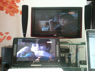
Bottom line is, I now can watch TV anywhere in my house -- on my laptop, even on my mobile!! See this lenovo touch tablet showing Oreo Ad on Vijay TV:


I had always felt that I have everything I needed to do this, but it has not been that easy before I discovered all the right things. A simple way to put it would be: connect the video/audio output of the set-top-box to a TV tuner on a comp and stream it! But a number of questions need to be answered at every stage in this setup.

1. Video Output of Set-Top-Box:
I needed a video output that is in parallel to the one that connected to my TV. I don't want to plug out and plug in every time I need to stream TV content. Fortunately, I have been using the component video of the STB for my TV due to its greater clarity, so the composite video was idling anyways. Cool.

2. Audio Output of Set-Top-Box:
I had to use a splitter here, as the stereo audio output is connected to my home theatre already.

3. Connect it to the TV tuner:
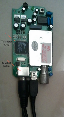
It is this stage that took me a while to figure out!! I had a TV tuner that I used and hacked long back. When it looked like everything was in place, I realized that the TV tuner only has a S-Video input and a RF antenna (cable) input. I would need a composite input socket and there is no easy conversion possible from composite to S-Video (ie., pin to pin mapping) due to the difference in the signals. I opened the TV tuner box and searched for any composite video input that probably didn't get exposed outside -- hoping I could solder them if required. This is the TV tuner motherboard:


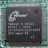
Could not find any socket/pin for composite video. I found the TV tuner chip on the motherboard ie., Trident TVMaster. On downloading the datasheet of the chip, I could confirm that the chip in deed supports Composite video as input. The pin diagram in the datasheet had clear indication of I/O pins available for composite input. When I traced those lines from the chip on the motherboard, it ended up in the existing S-Video socket. This kind of contradicts! How could S-Video port provide a composite input?! After lots of reading, the conclusion was simple : my TV tuner uses a non-standard 9 pin S-Video socket (while a standard S-Video socket is just 4 pins -- Y, C, Gnd, Gnd). The 9-pin socket is compatible with the 4-pin S-video socket, so the remaining 5 pins could be used for other inputs. Some hardware (like my TV Tuner) use this for simplicity in its form-factor. So all I needed was a conversion cable from composite video to 9-pin S-Video -- note: this is just pin mapping, no real signal conversion. Fortunately got this simple cable from ebay. I had reached this point months back and the project stalled :D

4. TV tuner works?
I had used this TV tuner against RF cable earlier, but never used/tested with composite video; and given all these conversion thingy, I wanted to first test if the TV tuner software works directly. And, yes it did!! I just had to configure the software to use the correct input signal. But TV tuner software doesn't stream, it just renders locally.

5. Stream it from VLC:
TV tuner device creates a video device on the computer and the tuner software uses the same. My tuner creates a Video device called 'Trident Analog Video'. VLC supports playing/streaming of video devices via DirectShow. I had streamed webcam's earlier, so wasn't anything new here for me. Things that required attention was how to configure via VLC, to use the correct input (Composite) -- as this device supports multiple inputs (RF antenna, S-Video, Composite etc). VLC has 'advanced options' while streaming that lets us configure the device. Input signal had to be set as '1' for composite. Used 'avi' as the container, 'divx' as video codec, 'aac' as audio codec. I have a Asus EEEBox on my setup that is already connected to the TV for other usage. Due to its proximity to the set-top-box, I used my eeebox for this purpose too. It connects to my home network via Wifi, so it could be reached from anywhere in my house.

6. Play it from VLC:
Now that the stream is on, all I need to do is connect to it via network. I used VLC again from a Lenovo touch tablet and connected to the eeebox via Wifi. Voila! I could now watch TV on my laptop. I'm yet to figure out an app for Android that could show multimedia stream over network -- given the small screen size, I am not that keen on watching TV on mobile. And as it has to go through the whole process of capture/encode/stream/network/decode/render, there is a delay of few seconds against the video on the live TV.

Some of you might have already thought about this: the only missing thing is that I can't change channels remotely. But it is just because I don't have a network remote, yet! (I have been eye-ing on Logitech Harmony Link for sometime :D).