Sunday, April 19, 2015

Arduino over Wifi via ESP8266 module

Arduino is pretty handy for low powered projects and is cost-effective (against Raspberry Pi). Not being able to connect to a network natively is a big challenge in applying Arduino for most use cases. While, Arduino has a Ethernet Shield for quite a while, it is impractical to expect a Ethernet port at every point an Arduino would be required. I do have Ethernet-over-Power (EoP) at home to extend its reach, but still didn't scale for me (the over all cost will also include a EoP adapter).

ESP8266 is an effective way to connect Arduino to a Wifi network. It is not a Arduino specific shield. It is a general purpose module that could be mixed with any other micro controller unit/circuit. All you need is a UART communication support on the other end (which almost all micro controllers have built-in). The added advantage is the cost, form-factor (unlike other shields) and just uses 2 pins from the Arduino (RX/TX of UART). The ESP8266 module is pretty small, but does its job well.
ESP8266 Wifi Module

Once powered appropriately, you could communicate with the ESP8266 module via serial communication (@9600 baudrate, at least my version of ESP8266). The Wifi configuration/data everything is then communicated via the extensions to a standard AT command set. This being UART based, its going to be imposing restrictions on the rate of transfer of data (but might not matter for most use-cases) -- just to highlight the difference against a USB or SoC based Wifi implementation.
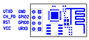
ESP8266 PinOut

The module does have a built-in TCP/IP stack, so we don't have to worry about that -- that's why we do get response to ping automatically (as shown in the video below). It is not full-fledged though; provides basic connectivity over Layer4 -- good enough. It does have its own DHCP client as well.
There is a open-source library for ESP8266 for Arduino:


This is what I used, except for few fixes that I had to do. Some of the AT commands were differently used in the library. 

Refer to ESP8266_WiFi_Module_Quick_Start_Guide for more up-to-date AT commands.

Here is the video showing my project in action :) Arduino joins my home Wifi network; shows its own IP on the LCD; runs a TCP server at port 1555 and waits to accept new connections. I connect from my desktop Ubuntu and send a message which shows up correctly on the Arduino LCD.


This is going to be a cool extension to my geyser control project now -- I should be able to control my geyser from anywhere and more importantly time it based on the needs. Some sort of security needs to be worked out.

Sunday, February 08, 2015

How I troubleshooted a tripping MCB

A tripping MCB is nothing uncommon and I have troubleshooted the faulting device many times before, but this time was interesting and challenging; hence the post.

We had this nagging issue of our master MCB tripping every time we turn on the ceiling fan in one of our bedrooms. To complicate the problem further, the fan is a designer fan and has 3 light bulbs and a built-in speed control (via hanging strings). So the faulting electrical component could be one of the bulbs, OR the speed-regulator inside the fan, OR one of the fan's electrical components (capacitor, coil etc.,), OR the speed-regulator on the switch board OR something that I didn't think of then.

The regulator on the switch board was the least of my suspects, as my first suspect was the bulbs (hunch!) or something in the fan. Removed the bulbs and tried, no use. Opened the fan's casing and looked for any obvious burns or something -- no sign of any electrical fault. This doesn't rule out a problem with the fan, but I wanted to cover all easy approaches before getting into disassembling a fan.

Just decided to checkout the switchboard. As I opened the switchboard, it was evident! As you see below, I could see a burnt regulator casing with some internal leakages.


It appeared like, this was the issue. Since our fan has a builtin regulator and I didn't have a spare one handy, I decided to short the regulator off the circuit and use the fan's strings to control the speed. Changed the wirings quickly and tried, and Viola! the fan is running normally without tripping the MCB. Even the fan's built-in regulator worked.

(Pic: had just taken the regulator off the circuit) 

With sense of satisfaction, I switched off the fan and closed the switchboard completely and screwed it tight. All done, so wanted to try for one last time that all is well. I turn on the fan, and the MCB trips! Wow, that's something :)

I had to stop for a while, as I couldn't come up with a theory for this. As you might know, the typical household switches control only one polarity (typically phase/line), the neutral goes to the appliance (fan) directly. The possibility of a short-circuit inside a switch board is pretty less (except if the switch board has a high amperage plug or something, that controls both polarities). And in this case, the MCB trips only when I turn on the fan. So it should be something related to the switch, but the switch has only one polarity! I was pretty sure, I'm missing something, because I couldn't explain the behavior.

The hint I got was the fact that, it all worked until I closed the switchboard. I just realized that our MCB also has Earth Leakage Protection. So it's probably not a short, but earth-leakage. On a closer look at the wiring that goes off the switch, towards the fan, I could find this:


In one of the joints, the insulation had burnt a bit, exposing few strands of the wire. When I closed the board tight, these strands came in contact with the metal casing inside the switch board, which is grounded. This triggers a leakage on the earth line and the MCB trips. I just had to redo the insulation with new tape, and that was it. The fan is running fine since then, without tripping the MCB.

Sunday, December 14, 2014

Home Automation: Arduino controlled Geyser

A long-pending post. I had built this project way back in May 2014, during the summer (in India). In one aspect, it seems better to have delayed this post, as my project has gone through a few bug fixes and enhancements, both in hardware & software -- so I can talk about the most recent version.

I had done a few other home automation stuff earlier like this one : DIY: Raspberry Pi controlled Power Strip - Part 1. I was/am constantly on the look out for any opportunity to automate things at home. We have been wasting lots of energy, as our geyser almost runs till cut-off most of the times and we won't need so much hot water during summer. This was simply because we won't remember to turn it off on time. I wanted to fix this by building a timer controlled switch for the geyser using Arduino.

I had earlier used Raspberry Pi for home automation. This time, I wanted to use Arduino for a few reasons. Unlike the power strip, which is completely network-controlled, this is a low power project and doesn't necessarily be network-controlled (I could actually snap in a Ethernet Shield for Arduino and make this network-controllable -- remember, I have Ethernet running over my power lines anyway, so easy to get a network anywhere). I also wanted to explore Arduino as part of this, as Arduino is relatively low cost and very low power (< 1W). I buy Arduino/Raspberry Pi from Ebay India directly (though they could be cheaper by other channels).

Here is the circuit:

This circuit was drawn using some online tool (that isn't perfect). The tool had bugs, so some of it didn't come out the way I want. Still conveys the idea.

The project is primarily, a relay (Relay2) driving the high power geyser (ours is around 2500W). The original plan was to drive this relay by a signal from Arduino. The high power relay that I procured, required a signal voltage of around 9V without which it couldn't really turn on the load. Arduino GPIO pins operate only at 5V. So I had to introduce another relay (Relay1) to supply the required 9V (external source), but on signal from Arduino. This also ensures, not much current is drawn directly from Arduino. Arduino Uno has a built-in voltage regulator (safe up to 12V), but I decided to be safe and use a custom voltage regulator using LM7805 (I wouldn't want to heat up Arduino or burn it -- lot cheaper to build an external voltage regulator - around Rs.70). I also have a 16x2 LCD to display the status/timer (see photos). The LCD is driven using the standard Arduino LCD library.

Here is the voltage regulator (built separately and tested out):


It doesn't turn on the geyser instantly. It runs a 10 second timer before it turns it on. This is to ensure that any electricity interruptions don't turn on/off the geyser too quickly. Better for the geyser.


Showing the countdown to shutdown:


The project in action (for the last 6 months). The USB cable connects to the data port of Arduino via a hole in the case -- this is used for software upgrades in-place; just connect my Mac and click on a button to flash it instantly with new code. eg., Once the winter started, I had to patch it to increase the timer a bit to get it to the right temperature.


This board is in series with the geyser, so turning on the physical switch doesn't turn on the geyser (expected).

Thursday, April 17, 2014

Fixing a bricked TP Link Ethernet-over-Power Adapter

Though I have Wifi coverage throughout my home, for better bandwidth and lower latency/packet loss, I also run a Ethernet over the electric line (230VAC) using the Ethernet-over-Power (EoP) adapters. I have been using this for few years for high-speed connectivity across different rooms without having to lay new Ethernet cables. (eg., my home theatre system connects to my NAS via EoP to play HD videos without jitter over network).

This is the exact model I use:


One of them went dead last year, so I had to buy 2 more to provide enough coverage. They aren't that cheap and aren't available in India directly (though I could import via ebay or amazon). Few months back, another one went dead. When I say dead, it would not power on, when you connect to the power line; no LEDs will glow and will be functionally dead as well. 

This wasn't scaling (I can't keep buying new ones) and I didn't know what was wrong so I can prevent this. As it was anyways dead I decided to break it open and figure out what had happened (maybe just a fuse blown?). That's where it all started.

Unfortunately I don't seem to have photos during the disassembly (not sure why I didn't shoot). This was one of the hardest disassembly ever, for me. It is meant not to be opened. There is one screw at the back (hidden under a sticker). Unscrewing that doesn't do much, although required. The packaging is very rigid, you can't even break it easily. I drilled a small hole on this, using a Bosch drilling machine to peek in a bit :D yes, it was a risky thing to do. The white cover is locked on to the black case with notches in the sides -- I had to peek into the the heat vents to figure this out.  Using a thin screw driver as wedge, I could open the white cover revealing the mother board inside.

It runs of a proper ARM-based Atheros chip, along with a (expected) RealTek chip for Ethernet support. I could only see the top of the board, and most of the board's soldering was not accessible at this point, so I couldn't test any of the circuitry for faulty parts. I had to take the board out. Be careful if you are doing this -- as I figured out later that the board had been glued to the black case below; so it wouldn't come off the case easily. You need to apply force along the sides and take it off. There is no other screw, I can tell you now (this was my biggest scare, that if I miss a screw, the force might break the board).

With quite some struggle and care, I took the board off the case. This is how the back of the board looks:


Arrows in yellow, show the gum that was holding the board to the case. At first, I even thought if this was some sort of leakage from the underlying components.

This is how the top side of the board looks (yellow wire was soldered by me to test the board outside):


The arrow on the left points to the fuse. I tested for continuity and it looked ok. Then started testing  each capacitor. The 3 capacitors at the bottom right were seeming to be faulty (short on DC). I was a bit surprised to see all 3 capacitors being blown -- on further investigation, they were in parallel in the circuit and even one faulty capacitor could project all 3 to be faulty. When I looked at the back side of the board (red-rectangle as in the backside-view picture), I could see some leakage on one of the capacitors. The capacitor also had a slight bulge at its top (no photo). I was more hopeful then. On soldering out the capacitor, off the board, the other two capacitors tested normal -- Good!

This was the faulty capacitor:


Now I need to get a spare cap with the same spec. Ebay India came to rescue. Ordered 10 capacitors 1500uF/10V and were delivered in 3 days.

The above top-side picture actually shows the board with the new capacitor replaced. Packed it in and did one final round of testing before I packed it into its box.


Test success. And here it is the final working version back in action:


And that's how I fixed a TP link EoP adapter for Rs.10 :)

If you have one such dead one, give it a try. It is likely this cap issue.

Sunday, November 10, 2013

Fixing Raspberry Pi filesystem corruption

While Raspberry Pi is a computer in its core, it is treated like an embedded device in most cases -- we can't expect a proper shutdown of Pi in most cases. This results in corruption of the / (root) file system (ext4) due to unclean unmount. 

In case you have been reinstalling Pi on to the sdcard every time this happens, you don't really have to reinstall. In most cases, mount the card via a card reader and run 

sudo fsck.ext4 /dev/xxxx  [xxxx the device file of the root partition]

(I assume linux by default). This should fix the / file system and the card will let your Pi boot now. If this doesn't help, try fixing the /boot partition:

sudo fsck.vfat  /dev/xxxx  [xxxx - the device file of the boot partition]

That said, you don't really have to do this. The clean and guaranteed protection against this problem could be provided by mounting the filesystem as read-only. Thus the filesystem is completely intact and will have no chance of corruption. In most cases, this should be fine (unless you have a reason to persist something on to the root filesystem). If you still need to write something to disk, write it to a different partition so it doesn't prevent Pi from booting if that goes corrupted.

How to mark the / and /boot partitions read-only:

You could do this from Pi itself, or on a different machine. Just edit /etc/fstab and add 'ro' in the flags as shown below:

/dev/mmcblk0p1  /boot       vfat    defaults,ro                0       2
/dev/mmcblk0p2  /           ext4    defaults,ro,noatime        0       1

Now reboot the Pi and it should boot with both these mount points in read-only mode. You could do a mount to verify, it should look something similar to this:

/dev/root on / type ext4 (ro,noatime,data=ordered)
devtmpfs on /dev type devtmpfs (rw,relatime,size=216108k,nr_inodes=54027,mode=755)
tmpfs on /run type tmpfs (rw,nosuid,noexec,relatime,size=44876k,mode=755)
tmpfs on /run/lock type tmpfs (rw,nosuid,nodev,noexec,relatime,size=5120k)
proc on /proc type proc (rw,nosuid,nodev,noexec,relatime)
sysfs on /sys type sysfs (rw,nosuid,nodev,noexec,relatime)
tmpfs on /run/shm type tmpfs (rw,nosuid,nodev,noexec,relatime,size=89740k)
devpts on /dev/pts type devpts (rw,nosuid,noexec,relatime,gid=5,mode=620)
/dev/mmcblk0p1 on /boot type vfat (ro,relatime,fmask=0022, dmask=0022, codepage=cp437, iocharset=ascii,shortname=mixed, errors=remount-ro)
tmpfs on /tmp type tmpfs (rw,nosuid,nodev,relatime,size=89740k)

Note: Some services (like apache2) might fail to start, because they can't write to disk. You might have to check individual services to figure out what they are trying to write and resolve it appropriately. For eg., apache2 writes log files /var/log/apache2. It is best to disable logging. If there is not too much logging, you could map the log folder to /tmp (tmpfs -- as shown in mount).

as root:
mkdir /tmp/apache2 
chmod a+wx /tmp/apache2 
cd /var/log
rm -rf apache2
ln -s /tmp/apache2 apache2

There is no worry of file system corruption any more. You could switch off Pi any time. I have been using this setup (in my PowerStrip Project) for many months now, without issues.

Sunday, May 12, 2013

SSH to Raspberry Pi first time without keyboard/monitor

Applies to "wheezy" version, not sure about other versions.
 
Raspberry Pi is mostly used as a remote machine and usually not tied up with any keyboard or a monitor, as in my case. Whenever you reimage a version of Raspberry Pi, connecting through ssh doesn't work.

Raspberry Pi's latest images come with "sshd" enabled by default. However, during first boot, "raspi-config" script (from /etc/profile.d/raspi-config.sh) kicks in and throws up a UI on the screen for the user to respond. This doesn't timeout and doesn't let the boot sequence complete; you would notice that Rsbpi has joined the network, but one cannot ssh to it (as the startup is stuck at this script and sshd is not started yet).

Workaround:
Once you reimage the SD card, mount the ext4 partition just created on the card. This will give access to the root (/) filesystem of the "wheezy" linux. Comment out the following line from /etc/inittab on that / filesystem:

1:2345:respawn:/bin/login -f root tty1
/dev/tty1 2>&1 # RPICFG_TO_DISABLE

This disables auto-login of root and raspi-config doesn't run until an interactive login happens as root. Now you can boot the SD card on Rsbpi and you should be able to ssh to it. 

Worked for me!

Saturday, April 13, 2013

DIY: Raspberry Pi controlled Power Strip - Part 1

This post will cover some behind-the-scene details on what went behind making this power strip. Had been quite busy for a while, so couldn't make it earlier.

There were few questions that I had to answer before I was sure I could build this:
  1. How do I control 220V AC from an electronic circuit, safely? Can I do it right the first time so I don't blow up the raspberry Pi? Being completely a software guy, this was a challenge. This was the first part of the problem I solved as shown in my earlier post on Controlling 220v Bulb using Raspberry Pi.
  2. Can I fit this whole solution seamlessly into an existing power strip so it has a clean form-factor and intuitive to use? Finding one such power strip which had enough space to hold additional circuits was a challenge.
  3. Building software so I can remotely control the power strip over any device. I decided to go the web interface route, so I can do it easily from any device. The software I eventually implemented is based on RESTful APIs, so it would also be easier for me to write an Android app or any other app over this interface.

Controlling 220V AC from Raspberry Pi


One of the foremost requirements for choosing Raspberry Pi was that it has programmable GPIO (General Purpose Input / Output) headers, without which any electronic interfacing would be pretty difficult and inefficient. Most micro-controllers (including modern microprocessors do provide GPIO pins) for interfacing with other low-level hardware peripherals. The voltage on a GPIO PIN can be controlled by instructing the micro-controller. Usually a TTL low/high is used to signal 0 or 1. But it is totally up to the interface to decide how to interpret it. Raspberry Pi uses 3V3 TTL, which means a 3.3V for high and 0V for low. Specially when you are using the GPIO pins for input, make sure the voltage doesn't exceed 3.3V. For the power strip, it is only in output mode.

Relay is another important component. It is an electro-magnetic switch that is used to turn on or off the high voltage. Relays require slightly higher voltages (>=12V) to work. When there is enough current flow, an electro-magnetic coil gets magnetized and pulls off a lever to turn on the switch. When the power is switched off, there is no magnetic field, and a mechanical spring pulls it back to its original position. Relay is a mechanical device and might suffer some latency and noise during its operation. It is not meant for high-precision control, but in my case this is good enough.

Since relays work on higher voltages and that it requires substantial current, a relay cannot be driven directly from a Raspberry Pi. It is very common to use a transistor as a switching device to turn on slightly higher voltages and/or when you need more current. This allows us to withdraw very less current (only the base current) from the controlling source (in our case Raspberry Pi) and to use a completely different power source (>=12V) for the controlled device (in our case, a relay). I have plugged in a 12V power adaptor which provides sufficient current to turn on/off the relay.

This is the circuit that drives a single relay: (The core idea of this circuit is a very common circuit that is used to control a relay via a transistor. I have customized it to appeal for the given use case.)


Remember that Raspberry Pi runs off USB power. Model B has a cap of 700mA in the inlet and this current is used for the complete functioning of Raspberry Pi. Any current that we draw out of this, is expensive and we need to be cautious. Specially if you are planning to drive a load (say a LED) directly, without using a different power source. 

WARNING: As I learned, there is no fuse of any sort behind the GPIO headers -- so any incorrect use might blow the micro-controller, thereby making a Raspberry Pi brick. Take extreme precautions and ensure that you are fine with the current you draw/sink from/into the GPIO.

The GPIO18 is just one of the many GPIO pins that could drive this transistor. To turn it on, my code will set a HIGH on that pin, thereby raising the voltage on that pin to 3.3V. With the required V-BE (the base-emitter voltage) at 0.7V to turn on, for the 4.7KOhm base resistor, the transistor will just draw around 0.5mA current from the raspberry Pi. Even when multiple relays are ON, there is no risk of over-drawing current from Raspberry Pi. The Diode D1 provides protection against any reverse current that could occur at the moment the relay is switched off.

Raspberry Pi has a GPIO python library that we can use to control the GPIO pins with ease. By being able to control from python, I didn't have to go through the pain of cross-compiling every time I modified any code.

Snip of code:
#
#initialization
#
import RPi.GPIO as GPIO
GPIO.setmode(GPIO.BCM) # use BCM pin numbering
GPIO.setup(gpio_pin_number, GPIO.OUT) # mark for output

#end of initialization; following could be called multiple times.

GPIO.output(gpio_pin_number, GPIO.HIGH) # output high / 3.3v
GPIO.output(gpio_pin_number, GPIO.LOW) # output low / 0v
#
As simple as that. Based on the command issued remotely, my power strip daemon would choose the right gpio_pin_number and set it to HIGH or LOW appropriately.

This post is getting long :). So, more about the packaging of the relay board, associated software design, in the subsequent posts.